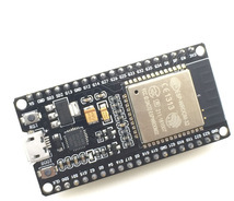
One of the most named technologies to be implemented for the Internet of Things, which has very striking features long distance communication and low power reflected in its low consumption, LoRa “Lo ng – Ra nge”, this type of modulation has been become very popular in data sending and receiving projects, there are some libraries already implemented for platforms ESP8266, Arduino, Raspberry pi and ESP32.
Recommeded: Getting started, considerations and concepts LoRaWAN # 1
Documentation of ESP-LoRa below.
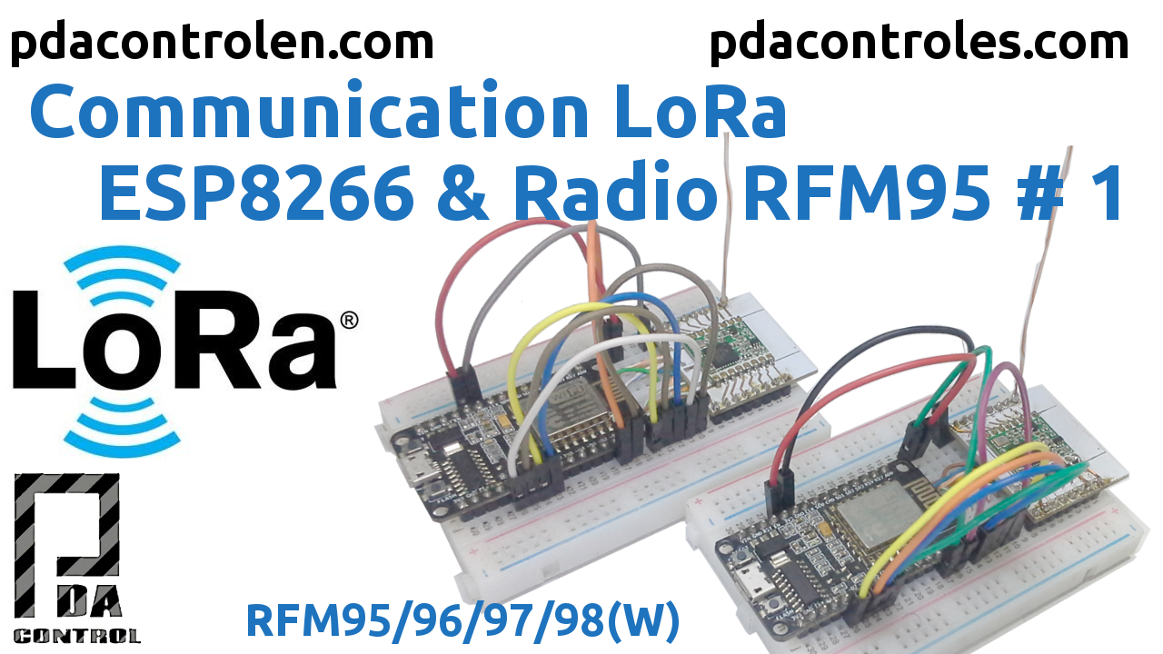
In this opportunity we will carry out a very simple test with ESP8266 and RFM95 LoRa.
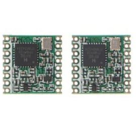
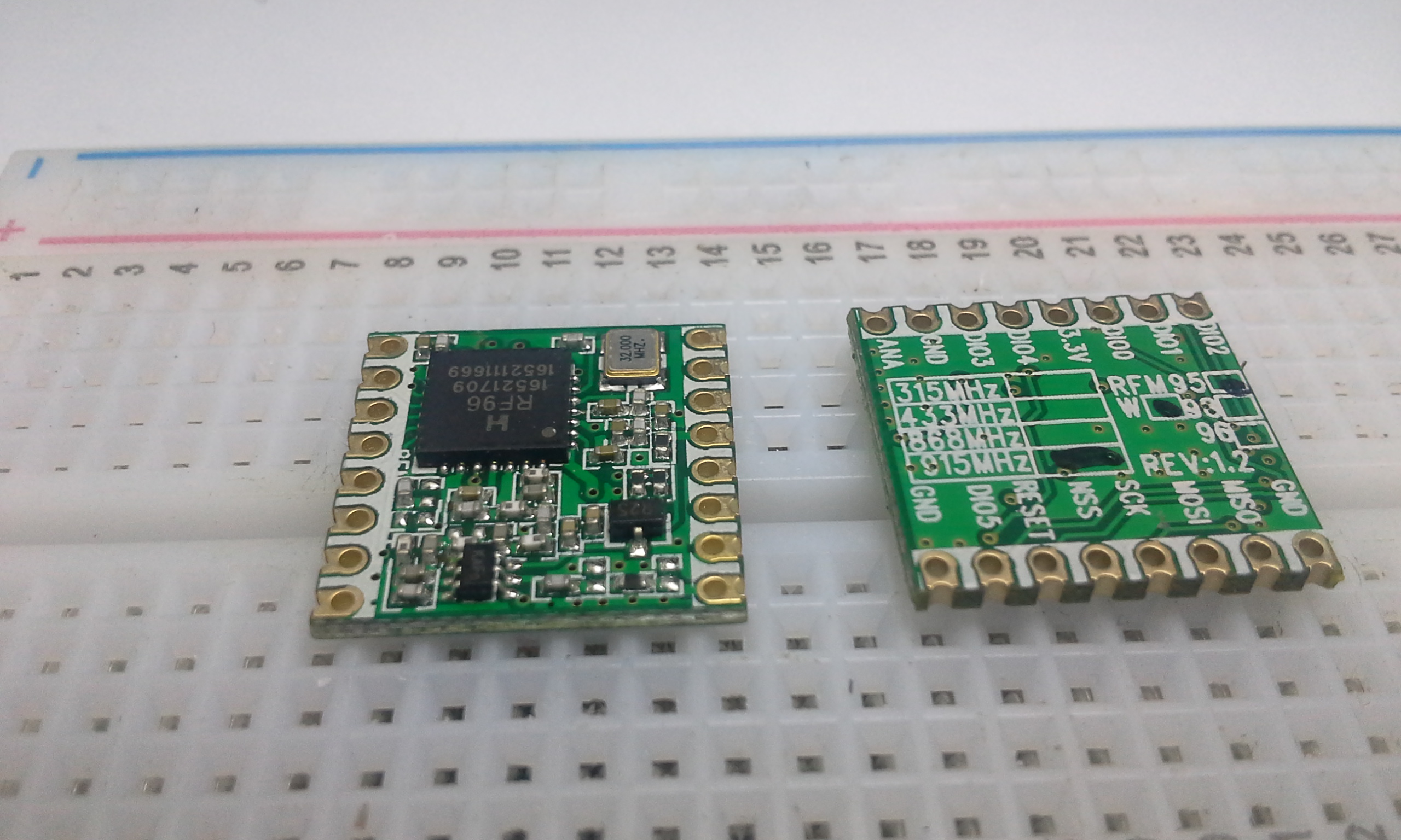
A while ago I got 2 modules / radios LoRa reference RFM95 of HopeRF, at a frequency of 915.0 MHz, then a tutorial recommended Introduction LoRa and the quick review to the module RFM95:
Introduction LoRa & Modulo RFM95 Hoperf
Tests Performed
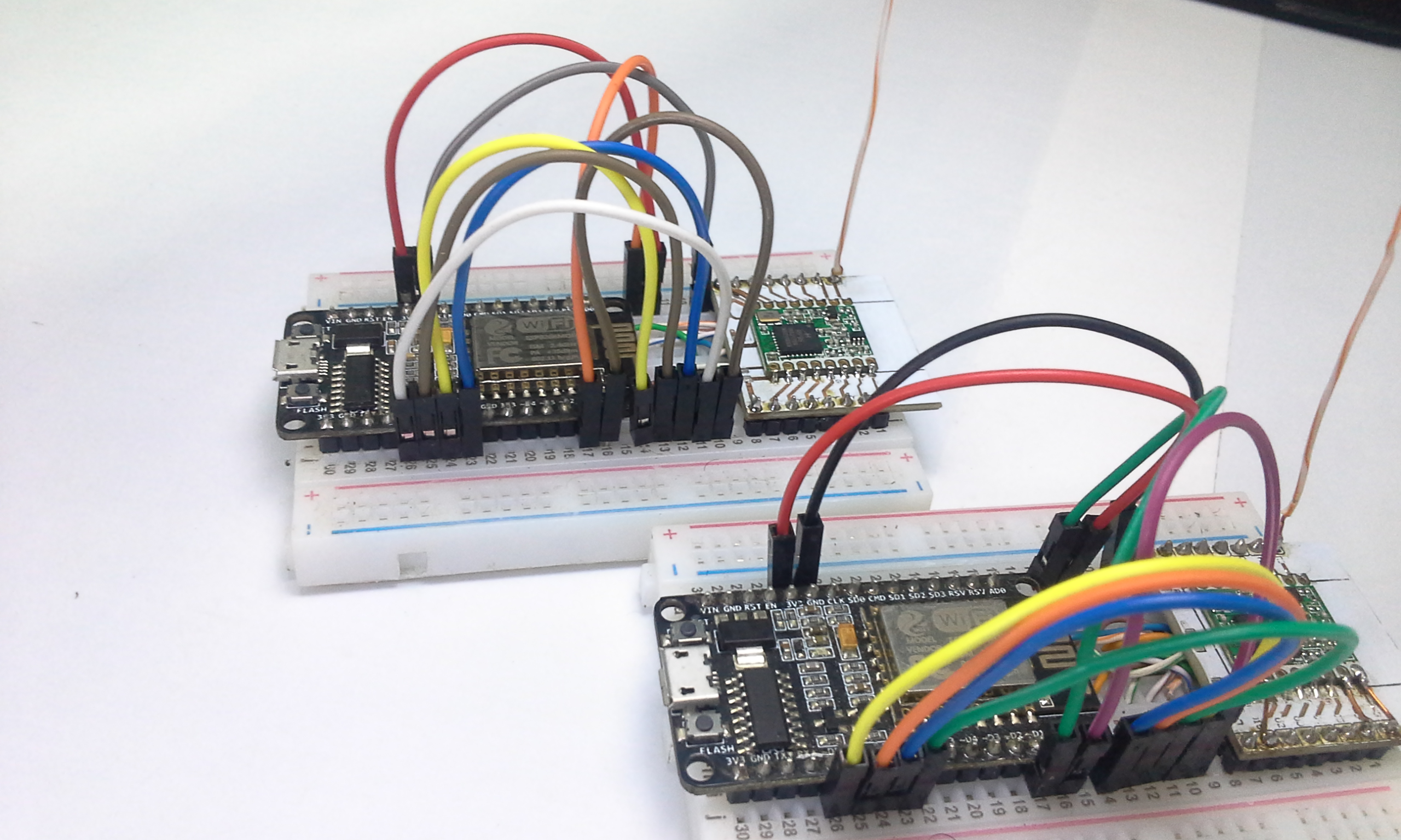
We will use 2 modules ESP8266 NodeMCU, which will communicate through the SPI bus with the RFM95 modules using the RH_RF95.h library of RadioHead, this test will be very simple, the sending of a message plus a counter from one module to another at 915MHz, Factory demarcation on the back of the PCB.
In this tutorial the LoRa modulation will be used, we will not implement LoRaWAN not to confuse.
In detail for this test only the LoRa modulation is used, LoRaWAN is not being implemented in this case, pending for future tests.
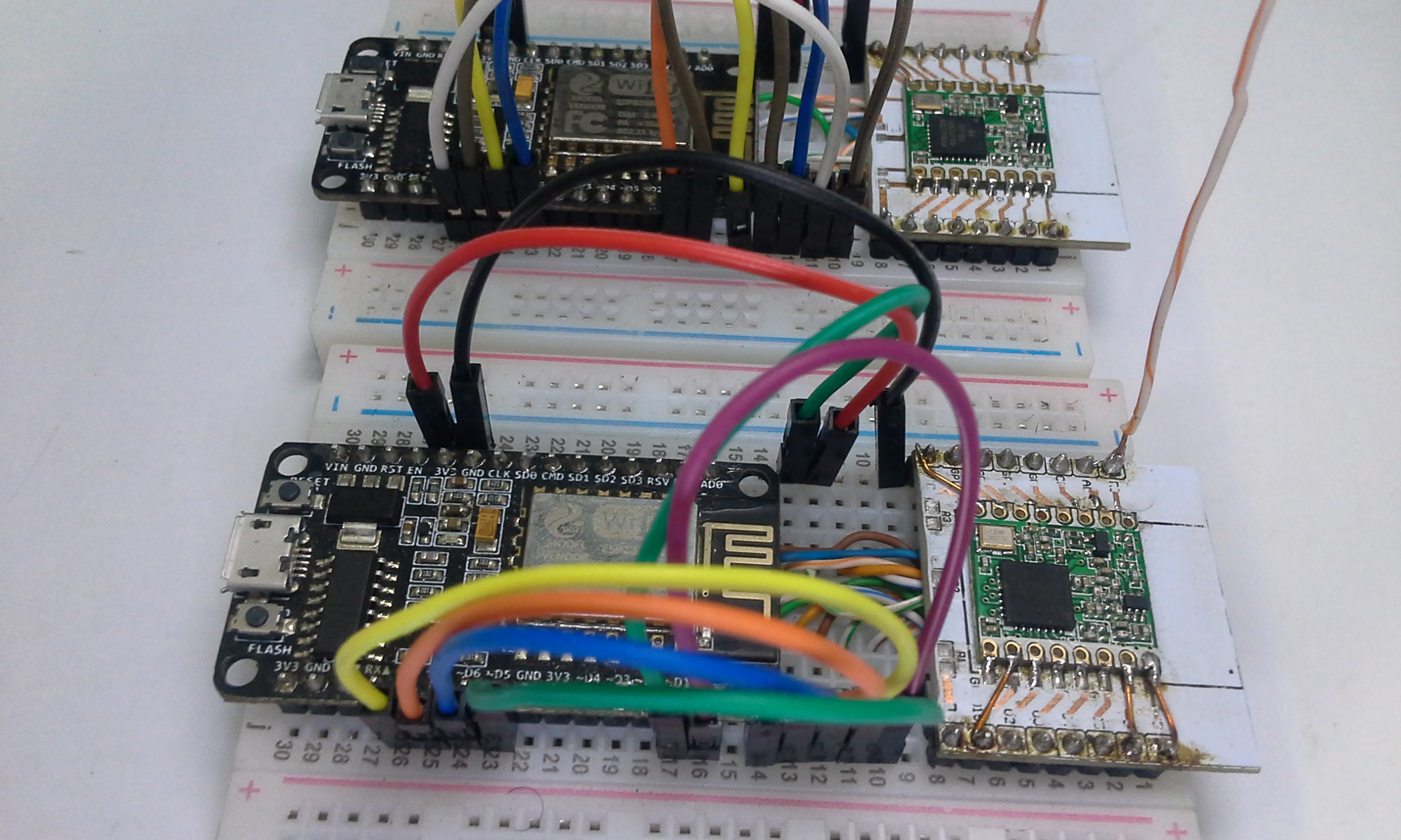
It should be noted that they already sell modules ESP8266 and ESP32 with modules LoRa a module / pcb but I think it better to perform a test with independent modules so that the test is more affordable when buying components and take into account the band / frequency of the module according to their area / area or region and regulations, complete information on legal uses LoRa.
An advantage, the design / pinout of the Radio RFM95 is compatible with white PCBs Adapters for ESP8266, facilitating protoboard mounting.
IMPORTANT: remove the 3 resistors and voltage regulators to the white adapter PCBs, to weld the RFM95.
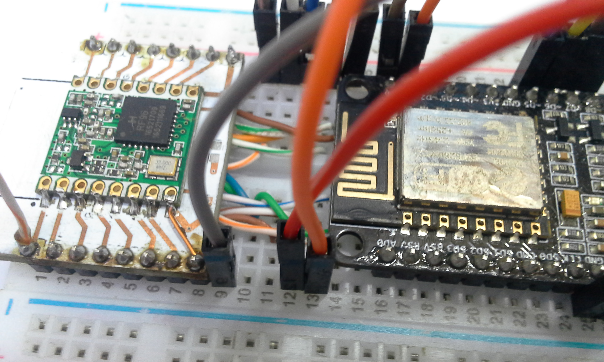
VERY Cheap Materials !!
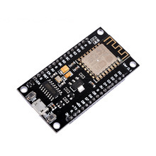
- 2 ESP8266 NodeMCU
- 2 Radio RFM95 ,in my case 915.0 MHz
- 2 white PCBs Adapters for ESP8266 12E/F
- 2 Protoboard
- Wire antenna, UTP cable, calculate length below
Arduino IDE Code
In this opportunity we will use the RH_RF95.h library of RadioHead, very used in examples of Adafruit for the test of its PCBs and modules, technically the module ESP8266 configures the parameters of the RFM95 through the SPI bus protocol.
Note: Download and / or github links below.
Since it is a very simple test, only the following parameters will be configured in both modules:
- Potency of transmission : 23 dBm = rf95.setTxPower(23, false)
- Frequency / Band: 915MHz = #define RF95_FREQ 915.0
Important the correct configuration of Pins for ESP8266:
- RFM95_CS = CS (Chip Selector or Slave Selector ).
- RFM95_RST = Reset Radio when initializing.
- RFM95_INT =Interruption from DIO0 output.
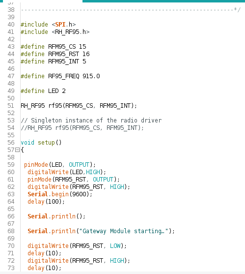
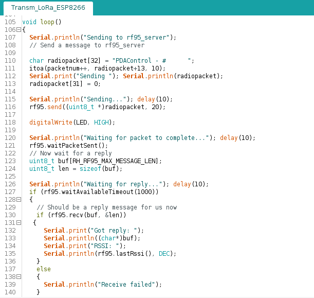
Example of Transmission Module # 1
The message “PDAControl -” and the value of a sent message / packet counter will be sent.
Note: Download and / or github links below.
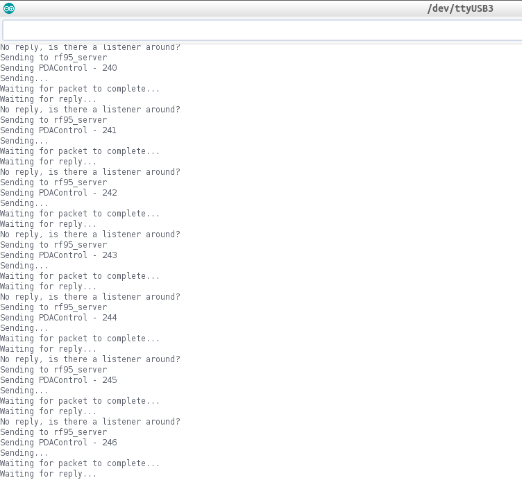
- Serial Terminal … Transmitting Message.
Example of Reception Module # 2
The module is in reception mode.
Note: Download and / or github links below.
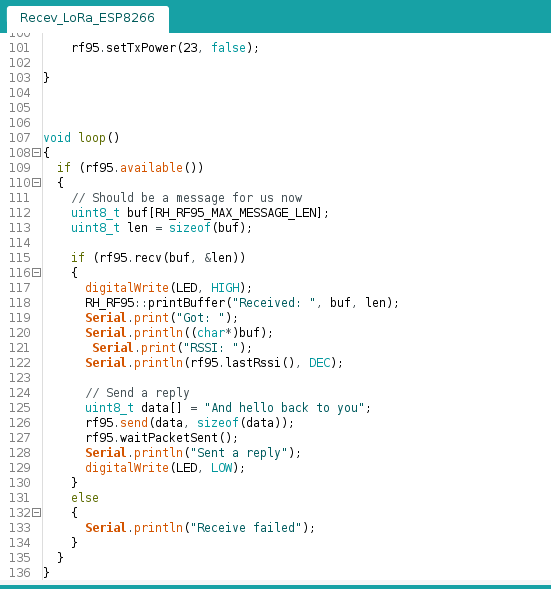
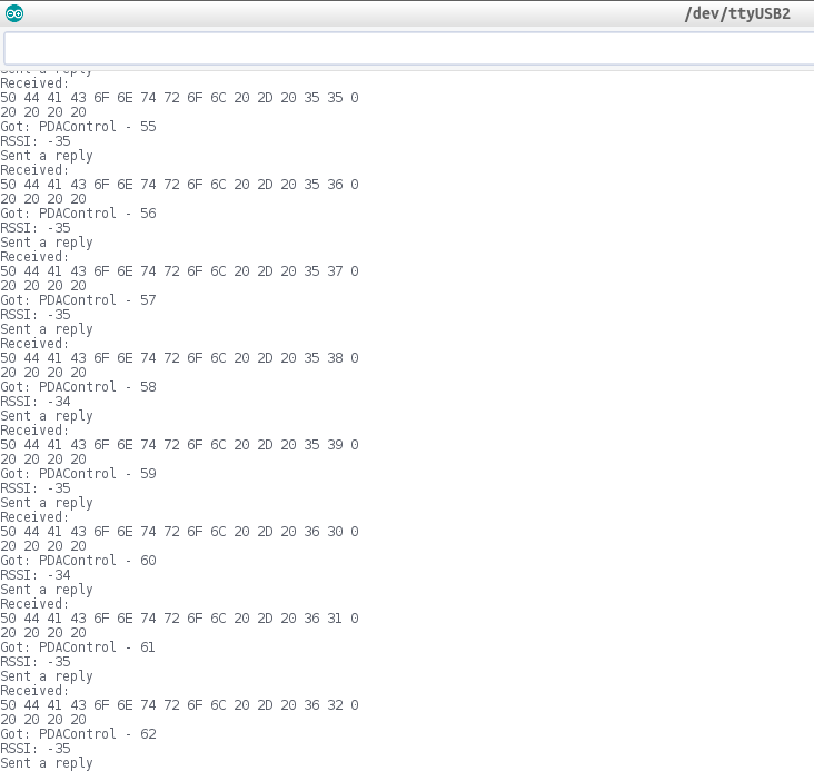
- Serial Terminal … Receiving, Message and RSSI
Antenna Manufacturing
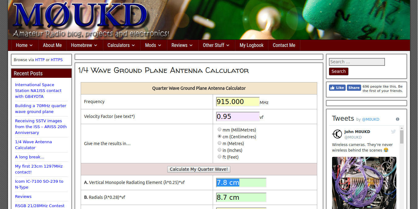
For this test the antenna has been manufactured with UTP Cable (Unshielded Twisted Pair) a 7.8 cm wire was taken, thanks to absolutelyautomation.com for the information, to calculate the length of the antenna, only I have modified the most important parameter Frequency, in the case of my module it is to 915.0.
Video: Communication LoRa ESP8266 & Radio RFM95 # 1
Connections
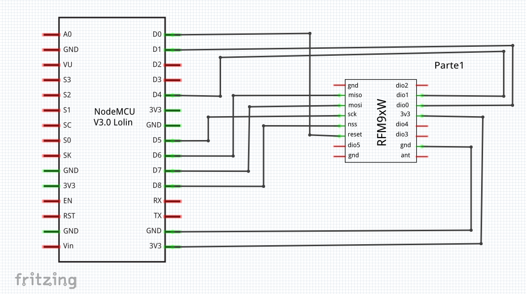
Note: The GPIO’s of Radio RFM95 works at 3.3v, higher voltages will burn them !!.
ESP8266 – RFM95/96
- Gpio15/D8 – NSS
- Gpio13/D7 – MOSI
- Gpio12/D6 – MISO
- Gpio14/D5 – SCK
- Gpio05/D1 – DIO0
- Gpio02/D4 – DIO1
- Gpio16/D0 – RST
- VCC – 3.3V
- GND – GND
Conclusions
As indicated previously in this test LoRaWAN is not being implemented, only the LoRa technology is being used, that is, only the modulation and communication of the radios.
Applications of this kind of projects, creation of Gateway LoRa-Wifi, for the sending of data from remote sensors to applications on the Internet.
Create sensors for long distance shipping under battery consumption and it is free, unlike GSM and 4G.
I would say that LoRa is the perfect technology for the Internet of Things.
In this case the Wifi of the ESP8266 12E will not be used.
In next tutorials we will measure the maximum distance with this kind of antenna and this module, I suppose that since it is a very economical and affordable module I doubt a bit of the 10 or 20Km in the open field and we will try to see.
Update Prototype ESP-LoRa
To advance in this project after many protoboard tests, I have created a PCB for esp8266 12e and the modules / radio RFM95 or LORA1276-C1, allowing the possibility of configuring as module LoRa and LoRaWAN – GATEWAY & LoRaWAN – NODE for possible connections with TTN or “The Things Network” IoT platform based on LPWAN networks “Low-Power Wide-Area Network”.
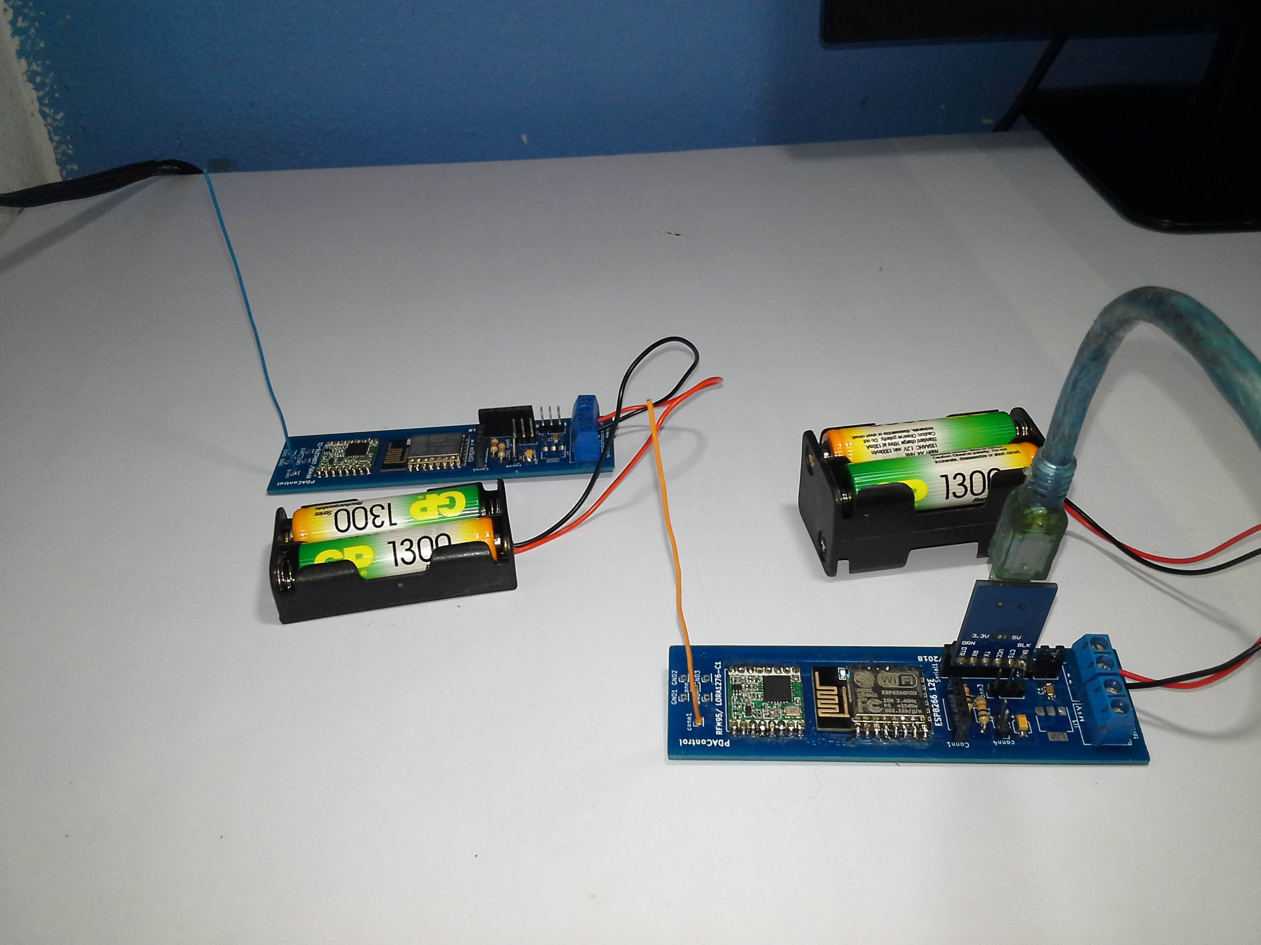
In the following tutorial I will indicate how to design 10 PCB prototypes with the company Seeedstudio with the help of KICAD.
Recommended : 10 PCB’s Professionals with Seeed Studio Fusion – ESP-LoRa Prototypes
10 PCB’s Professionals with Seeed Studio Fusion – ESP-LoRa Prototypes
Communication ESP-LoRa V1.0 ESP8266 & Radio RFM95 #LoRa
Recommended Tutorials
Internet Of Things (IoT) Using NiceRf LoRa1276 by absolutelyautomation.com
References
- Introduction LoRa & Module RFM95 Hoperf
- website: M0ukd.com 1/4 Wave Ground Plane Antenna Calculator
- Internet Of Things (IoT) Using NiceRf LoRa1276
Downloads / Github
