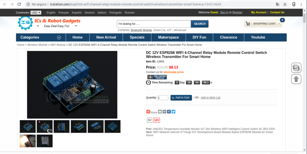
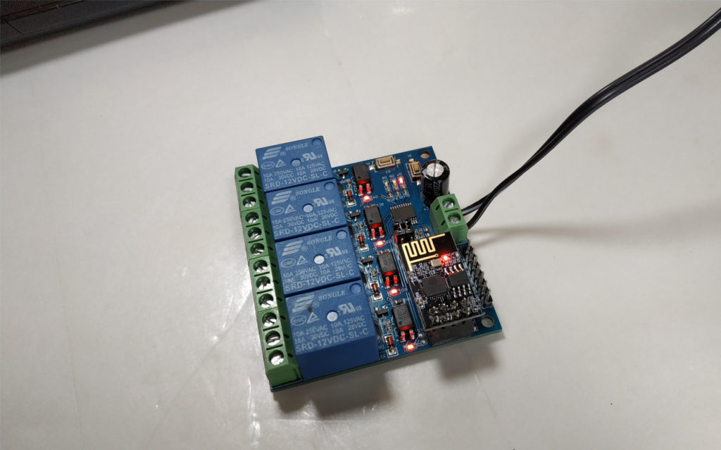
I have seen a large number of applications of ESP8266 modules controlled loads using Reles, it would take time to really design from scratch, so thanks to ICStation.com I have received an ESP8266 module with 4 outputs to Relay.
ICStation.com

ESP8266 WIFI 4-Channel Relay
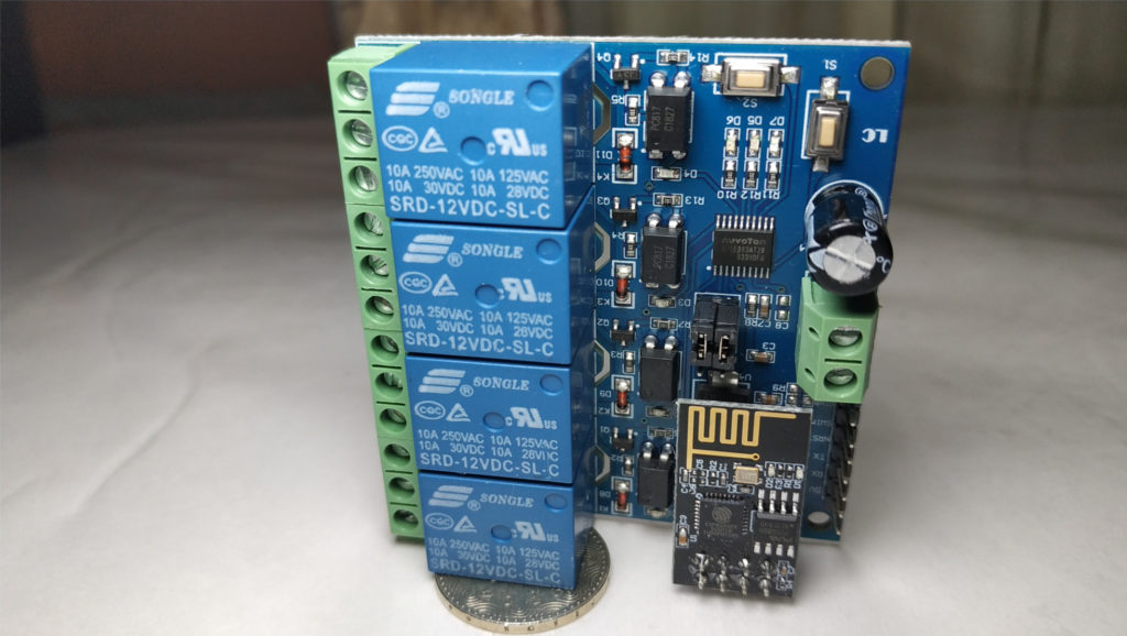
ESP8266-01 and N76E003AT20
It uses an ESP8266-01 module additionally uses an N76E003AT20 MCU (1T 8051 Processor) from Nuvuton Direct, which is responsible for receiving the ESP8266 communication and controlling the 4 optocouplers / Reles and the control of the indication LEDs.
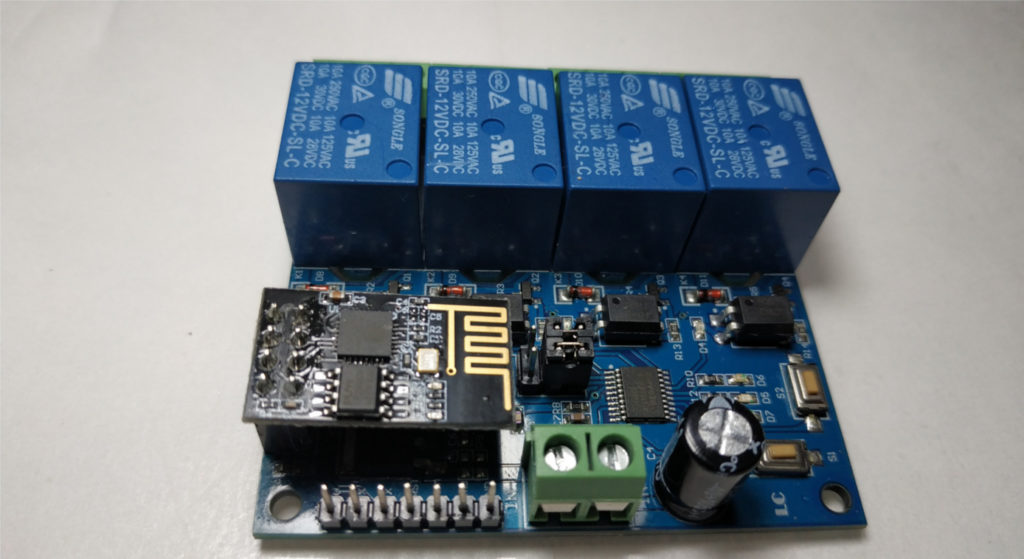
Characteristics
- Working voltage: DC 12V
- Charging voltage: DC 30V 10A / AC 250V 10A
- Working temperature: -40 ℃ ~ 85 ℃
- Working humidity: 0% ~ 95% RH
- Size: 63 * 60 * 20mm
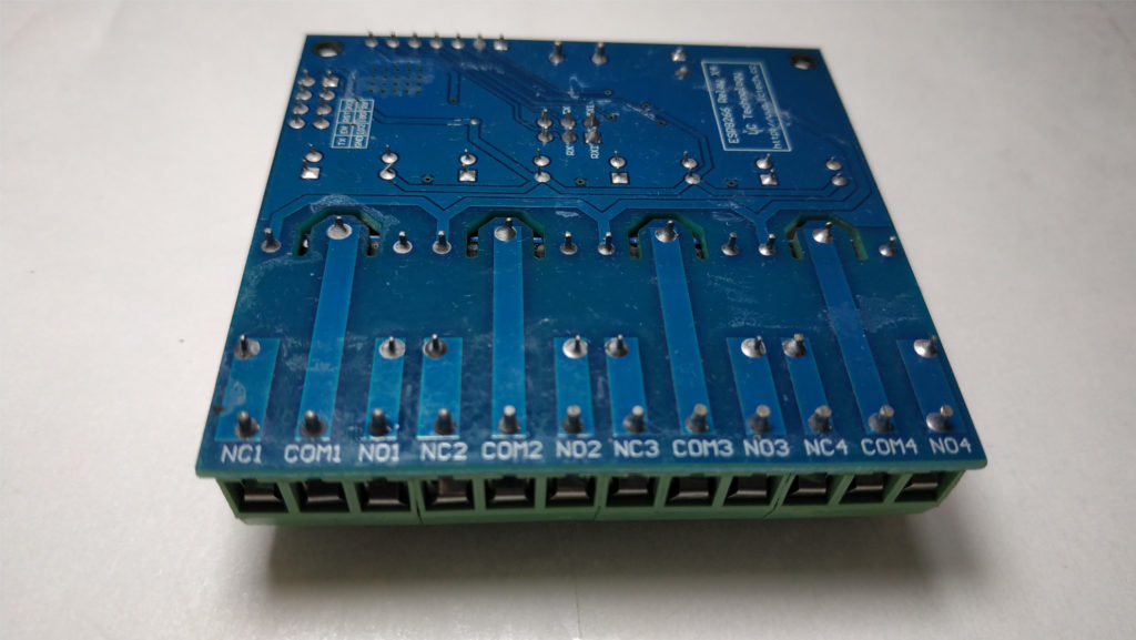
Where to buy it!
Functioning
The Rele module has 2 buttons for configuration:
S1: Configure Operation mode.
S2: Reset Factory settings.
Modes of Operation
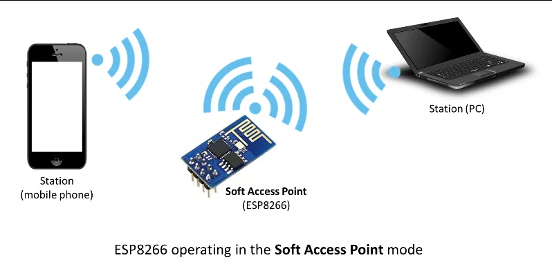
- The ESP8266 is configured in AP mode “Access Point” and our Phone / Tablet or Computer connect to it as a client or Station.
- The ESP8266 is configured in Client mode and can be connected to a Wifi or AP Network, even if our Phone / Tablet or Computer connects to it as a client or Station to that same Wifi Network.
It seems that additional applications such as EspTouch_Demo or EasyTCP_20 are required for configurations, I will not use any of these in our case we will use Node-RED.
Tests performed
Given this is the initial test, we will use mode 1, the ESP8266 as an AP and our device will connect to it as a client or station.
According to the documentation, each of the 4 relays requires an HEX frame to be activated and deactivated.
Turn Off First Relay A0 01 00 A1 [“0xA0″,”0x01″,”0x00″,”0xA1”]
Turn On First Relay A0 01 01 A2 [“0xA0″,”0x01″,”0x01″,”0xA2”]
Turn Off Second Relay A0 02 00 A2 [“0xA0″,”0x02″,”0x00″,”0xA2”]
Turn On Second Relay A0 02 01 A3 [“0xA0″,”0x02″,”0x01″,”0xA3”]
Turn Off Third Relay A0 03 00 A3 [“0xA0″,”0x03″,”0x00″,”0xA3”]
Turn Off Third Relay A0 03 01 A4 [“0xA0″,”0x03″,”0x01″,”0xA4”]
Turn Off Fourth Relay A0 04 00 A4 [“0xA0″,”0x04″,”0x00″,”0xA4”]
Turn On Fourth Relay A0 04 01 A5 [“0xA0″,”0x04″,”0x01″,”0xA5”]
ESP8266 Access Point Mode
For this test I will not complicate downloading applications, EspTouch_Demo or EasyTCP_20 will be another time, since we will connect directly to the ESP8266 you can quickly change that in AP mode, the ESP8266 takes the IP address 192.168.4.1 and any other device takes the address 192.168 .4.2 and using port 8080 we will send the HEX frame to activate or deactivate the relay.
Control from Node-RED
We will use the quintessential connection tool to control the Rele module.

Test
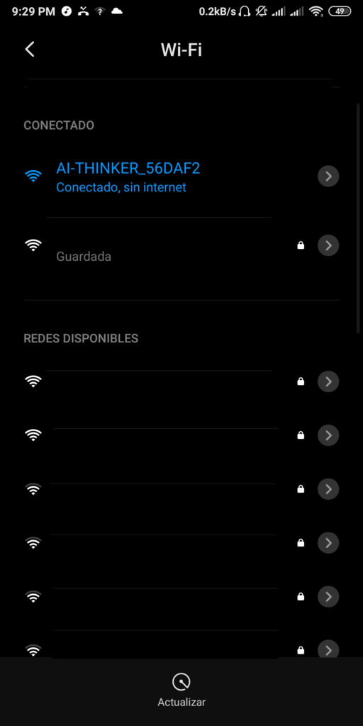
The ESP8266 module will generate a Wifi network similar to this:
AI-THINKER_56DAF2
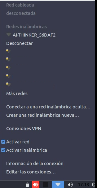
In our case we will connect our Computer (Laptop) via Wifi to that network which has no password:
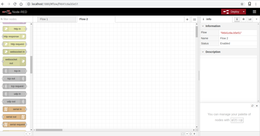
Previously we have installed Node-RED and Dashboard nodes.
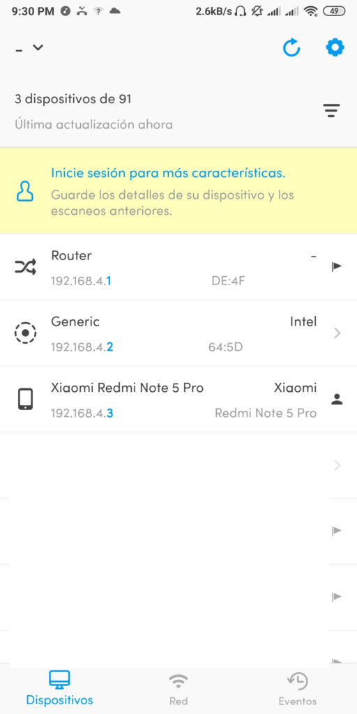
With the help of the Android application FING we can see the IP addresses, generated by the ESP8266 module, which takes the IP address 192.168.4.1.
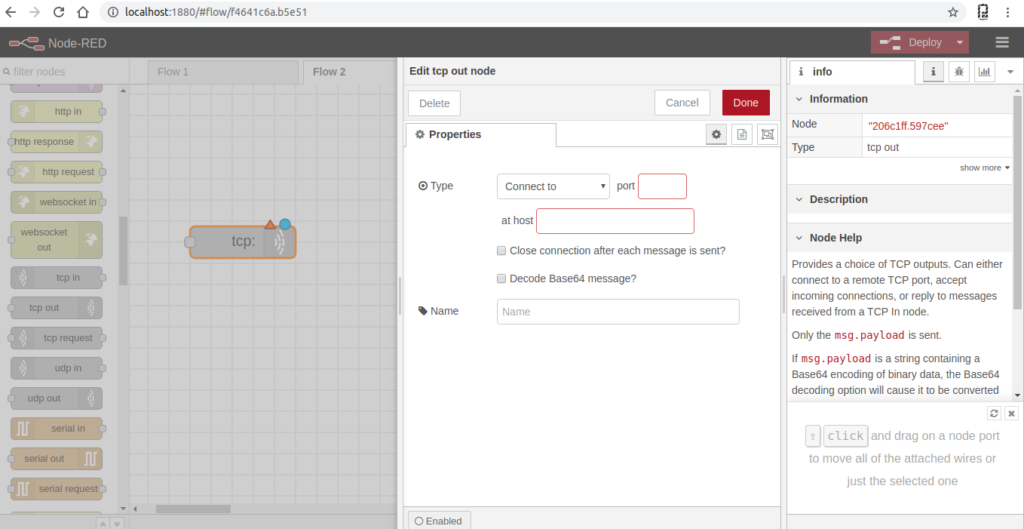
TCP/IP Out Node
This node allows us to send frames to an IP address and specific port:
Activation frames are sent to the IP of ESP8266 in this case, 192.168.4.1 port 8080.
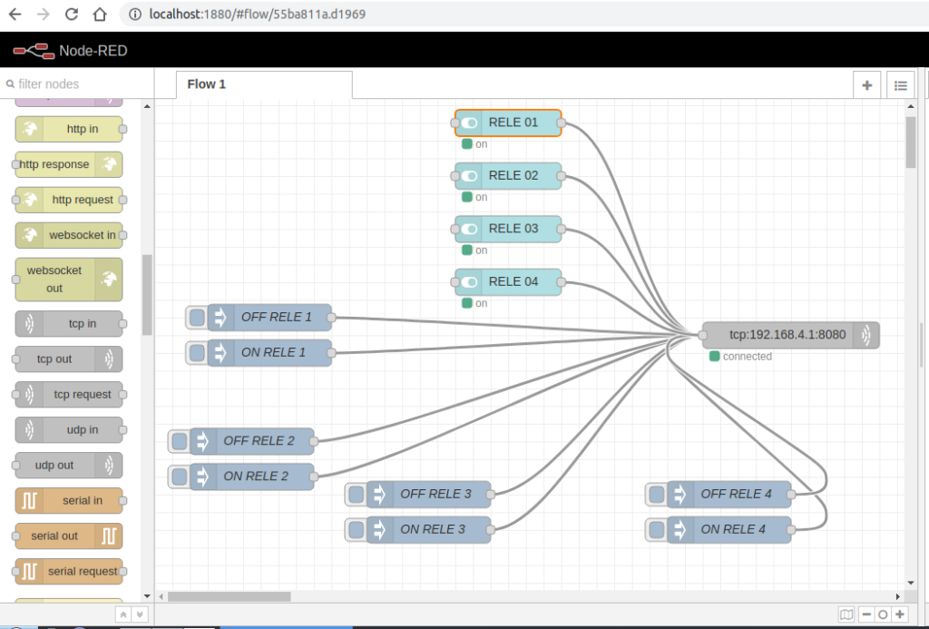
With Node-Red-Dashboard, a control panel has been created.
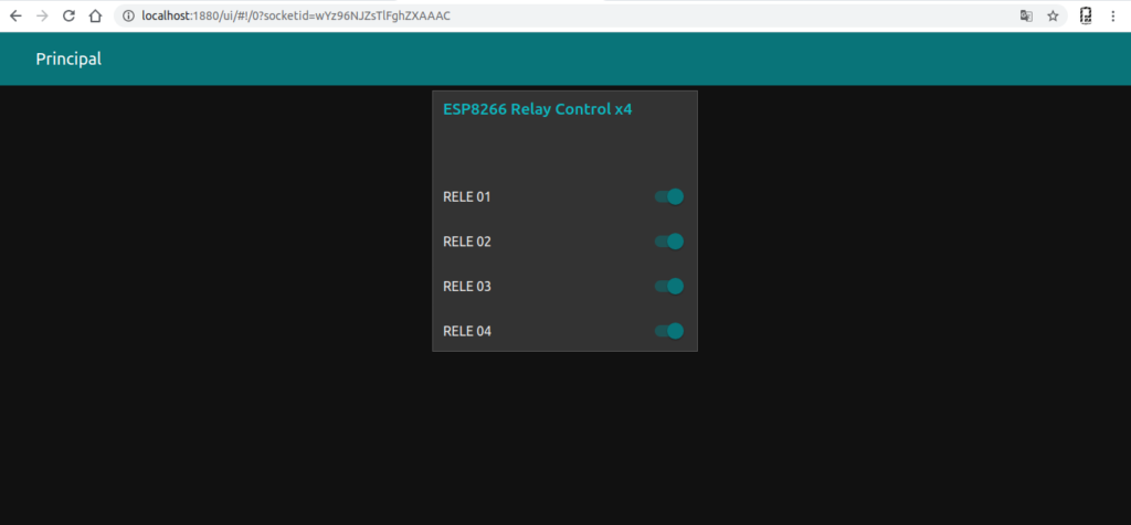
Reles activation test.
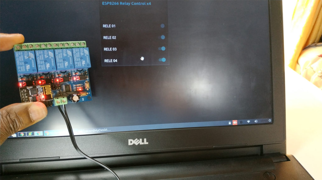
Video of Tests Performed
Conclusion
The module has a very good insulation concerning the control part and the power part.
Interestingly, the addition of an additional MCU for the control of the Reles, has the serial port available to reprogram the ESP8266.
I do not know the firmware that has the MCU N76E003AT20, possibly receive serial commands ESP8266
In next tutorials we will use it in station mode connected to a Wifi network, it would be interesting to use it in control applications, Domotica or IoT, creating a new OTA firmware and adding other protocols such as modbus or MQTT.
Finally thanks to ICStation for the ESP8266 4Relay module
Downloads
Importation File Node-RED
