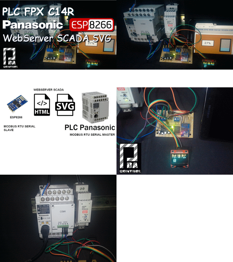
ESP8266 Scada SVG Modbus RTU Display Oled PLC Panasonic FPX C14R

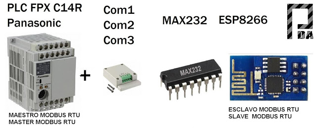
Taking up and improving the applicability of this project integration Scada Web-based SVG ESP8266, it has decided to communicate the ESP8266 with a PLC (Programmable Logic Controller) Brand Panasonic FPX C14R, atravez protocol Modbus RTU Serial RS232, Being the PLC Panasonic Master Modbus RTU and Modbus RTU slave ESP8266.
It has an integrated OLED display 128 x 64 communicated via I2C with the ESP8266 for visualization features of the modbus PLC registers.

General objective of the Project
1 ESP8266-01 module with Max232 will connect to the serial port RS232 PLC Panasonic.
2 Integrating Modbus master is routine in the PLC Panasonic with previously programmed strategy in Control FPWIN His Panasonic -Pro software, it is planned to create a monitoring solution Concerning Industrial Controllers values is PLC, PAC, HMI or OPC.


Project Specific Objective

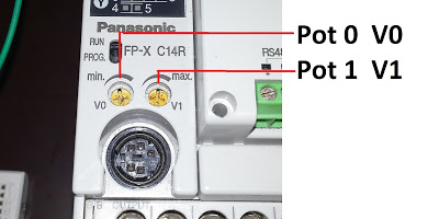
the value of potentiometer V0 PLC Panasonic in a range of 0-1000 escalizado in ESP8266 from 0 to 100% was displayed, the value in a Mini scada webserver based on SVG is visualized, the variation of the potentiometer is noticed almost instantly, for communication between the PLC and ESP8266 is via RS232 Modbus RTU.

 Potentiometers Panasonic PLC


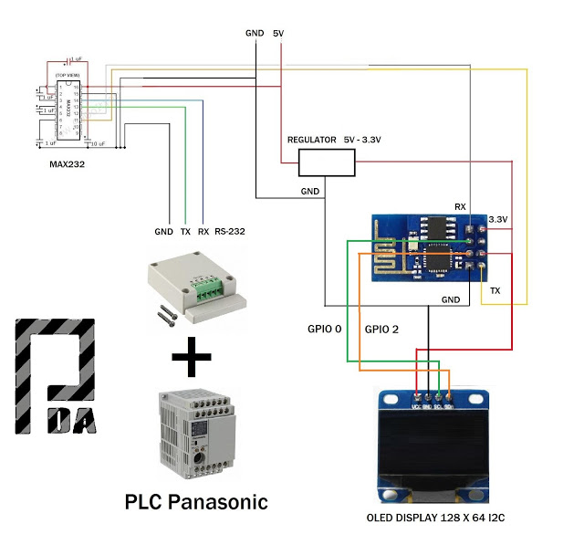
Diagram
 
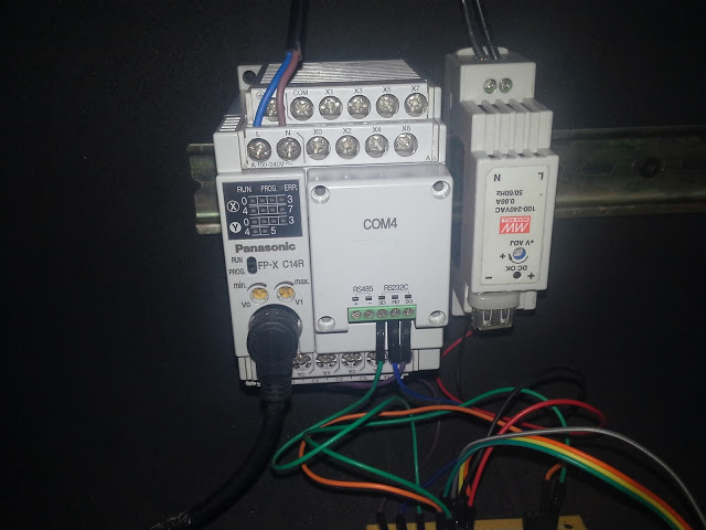
1  – PLC FPX C14R Panasonic + Comunication  Cassette COM4
 
By default, the PLC only has 1 Puerto Panasonic 5-pin minidin similar to the PS2 port, the communication port and / or RS232 port programming called Toolport, which can only be configured as:
1 general purpose communication (scales, barcode readers and serial printers)
2 Slave Mewtocol – FP series (Panasonic programming protocol)
Note: No toolport port allows configuration as Master – Slave Modbus RTU
COM4 casette is a expasion communication with 2 ports COM1 (RS485) and COM2 (RS232)
It was used COM2 (RS232).
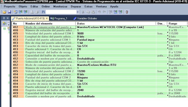
Additional port settings
 
Modbus RTU Master Routine
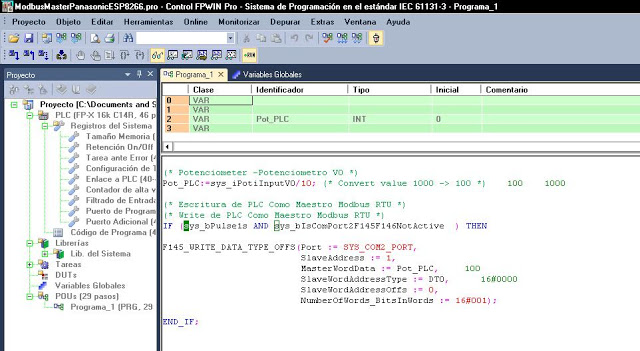
Control Strategy in FPWIN Pro


(* Potenciometer -Potenciometro V0 *)
Pot_PLC:=sys_iPotiInputV0/10; (* Convert value 1000 -> 100 *)

(* Escritura de PLC Como Maestro Modbus RTU *)
(* Write de PLC Como Maestro Modbus RTU *)
IF (sys_bPulse1s AND sys_bIsComPort2F145F146NotActive  ) THEN
 
F145_WRITE_DATA_TYPE_OFFS(Port := SYS_COM2_PORT, 
   SlaveAddress := 1, 
   MasterWordData := Pot_PLC, 
   SlaveWordAddressType := DT0,  
   SlaveWordAddressOffs := 0, 
   NumberOfWords_BitsInWords := 16#001);          

END_IF;


2 – ESP8266-01 + MAX232

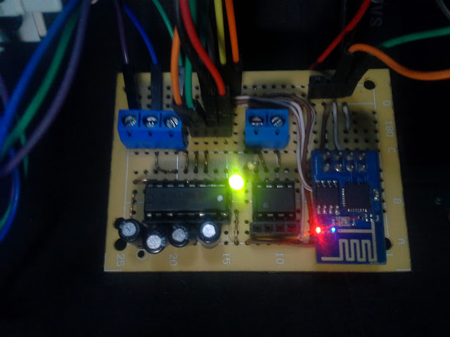
Has made the connection module for 3.3V TTL serial part to a MAX232 (TTL to RS232 converter) for voltage levels between the communication ports are the same, the module must not exceed feed this voltage 3.3v .


3 – HTML SCADA BASED ON SVG
 
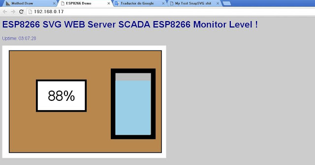
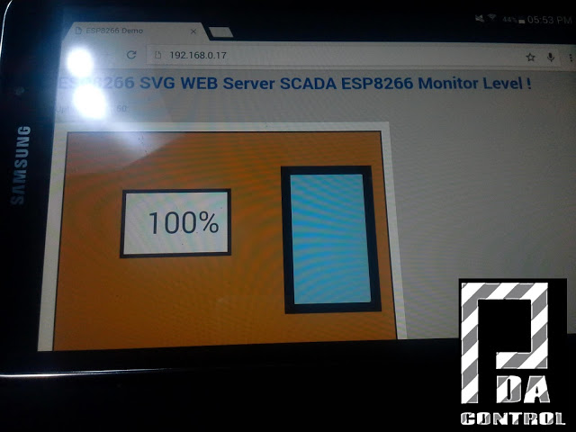
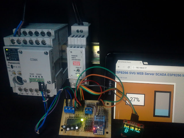
By typing the IP address assigned to the module ESP8266 from any browser will connect directly to this website which will display the following screen shot.
Technically an HTML web server (ESP8266) which seeks an SVG file created, modified and updated in the server root (ESP8266) is created, which makes the entire website is not updated only part that is the SVG this think it is allowing more dynamic to create the SVG directly into the HTML which would require upgrading the entire website.


OLED DISPLAY 128 X 64 + -ESP8266 – 01
It has also built an OLED display 128 x 64 connected to ESP8266 via I2C protocol, connected by GPIO 0 and 2, it has been added to make the value display in real time and allows it to be more
complete the test, the displayed value is the value from 0 to 100% relative to the potentiometer PLC.


Materials 
1 PLC Panasonic FPX C14R
1 Casette COM 4
1 ESP8266 – 01   very cheaps!!!
1 Display Oled 128 x 64 I2c
1 Supply 5 VDC
1  LD1117V33 Regulator 5v to 3.3v
1 MAX232
Video Complete Test

Leave a Reply