Thanks to the request of one of my subscribers I have created this tutorial, which will be written in a Panasonic PLC (Nais) of the FPX Series Family. These PLCs are very practical and a high percentage of machines have it as a unit control.
On this occasion I will use an Arduino MEGA 2560 R3 and a converter MAX232 (RS232) to write to DT records of the PLC, since in the network are the manuals of Mewtocol Protocol of panasonic that is used by PLC’S, HMI Screens, Inverters, Servo Drives Among other industrial devices.
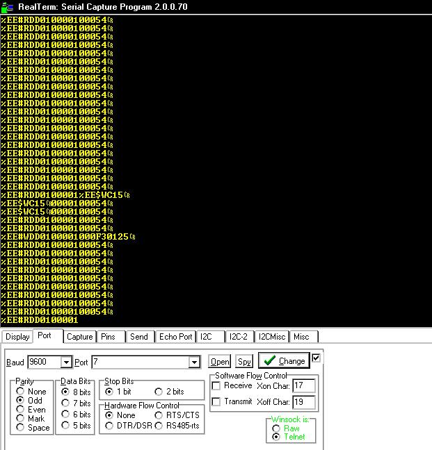
The Mewtocol protocol has similarities to Modbus, although the Mewtocol mixes Hexadecimal and Ascii in its frames, with 2 usb serial converters, 1 PLC and a panasonic screen, I take the task of spying physically the plot, understand it and replicate it in Arduino IDE.
Realterm
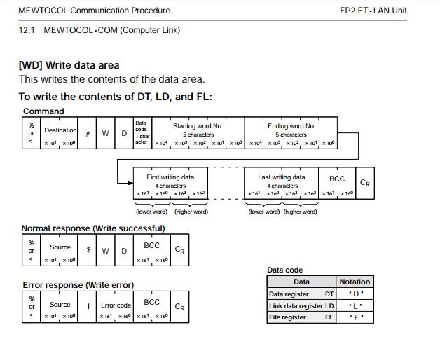
We have only implemented a part of Mewtocol, specifically [WD]write data area frames that write to only write DT, LD, and FL records, write only.
Description of Frame Mewtocol
This frame allows to write in the registers:
- DT Data Registers
- LD Link Data Registers
- FL File Registers
Arduino IDE
Funcion addcero
This function concatenates a series of zeros to the left “0000” to an input variable according to the maximum size that output is required and the output returns. Input parameters String (Variable to concatenate) int size or number of zeros maximum to add.
Example: addcero (“10”, 5) returns “10” + “000”.
 String addcero(String value ,int Max )
{
int Tam = value.length() ;
String ceroadd="";

for (int i=0; i < (Max - Tam) ; i++){
 ceroadd+="0";
}
value=ceroadd+value;
return value;

}
WD_Mewtocol Function
The main function is WD_Mewtocol that generates and sends the frame mewtocol, this function requires 2 input parameters:
String Register address, example “DT100”.
Int 16 bit value to be written to the “DT100”.
Header
Indicates the start of the frame and indicates the type of record on which to write:
Example:% EE # WD “+ Datacode (D or L or F).
////////////// Header - Encabezado /////////////////////////
String DT = "D"; /// Data Registers
String LD = "L"; /// Link Data Registers
String FL = "F"; /// File Registers
String Datacode = DT; ///// DT Registers
String Encabezado="%EE#WD"+Datacode;
///////////////////////////////////////////////////////////////
Type of Registration and Address of Registry
Separate the address of the record type and concatenate zeros.
Example: “DT”, “1000”,
String DireccionDT = RegistroDT.substring(2,6) ;
DireccionDT = addcero(DireccionDT,5);
Conversion of int value, Hex to Ascii
The value to send requires a process to add to the frame.
- We must separate the high and low layer from the value we use the functions highByte and lowByte.
- Convert both records from hex to String.
- Convert to Shift.
- Fill with zeros to the left addcero function.
////////          High and Low Value, conversion int to HEX and String
/////////         Parte Alta y Baja de Valor , conversion int a HEX y String
byte hi, lo; // 8 bits C/U
hi = highByte(valor);
lo = lowByte(valor);

String valorH=String(hi, HEX);
String valorL=String(lo, HEX);

valorL.toUpperCase();
valorL = addcero(valorL,2);// Add padding zeros left

valorH.toUpperCase();
valorH = addcero(valorH,2); /// Add padding zeros left
Full Frame Concatenation
//////////// Frame Concatenation ////////////////////////////////////
//////////// Concatenación de trama ////////////////////////////////////
Trama = (Encabezado + DireccionDT + DireccionDT + valorL + valorH );
Trama.toUpperCase();
///////////////////////////////////////////////////////////////////////////
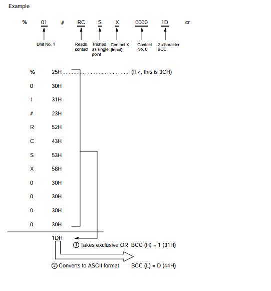
Calculate BCC
BCC (Block Verification Code)
– The BCC is a code that performs horizontal parity error checking to
Improve the reliability of the data being sent.
– The BCC uses an exclusive OR from the header (%) to the final character of the
Text and converts the 8-bit data into a 2-character ASCII code.
BCC at Arduino
We take the whole frame, and with the getBytes function we move it to a byte array and the for loop makes an exclusive or with the records and the BCC result we convert it to String and concatenate it to the end of the frame, if the BCC is Wrong the panasonic PLC will discard the frame automatically.
 int TramaTam =Trama.length(); // Longitud Trama // Length Frame
byte tram_arreglo [TramaTam]; // Array Bytes
Trama.getBytes(tram_arreglo,TramaTam+1); /// Stores Frame in BYTES Array

byte bcc = 0;
String BCC;

 for (int i=0; i < = (TramaTam - 1); i++){
 bcc ^= tram_arreglo[i]; /// exclusive or
 }
BCC =String(bcc, HEX); ////// BCC to String

/////////////////////Concatenate BCC to frame////////////////////
Trama = Trama + BCC ;
Trama.toUpperCase();
/////////////////////////////////////////////////////////////////
Send Frame
Finally we send the plot through the SerialPort1 and concatenate only CR.
Serial1.print(Trama+"\r");
PLC Response Confirmation
After sending the frame, the PLC sends a frame response, indicating if it is correct to send something similar to this “% EE $ WD12” and in frame error “% EE! 4202”.
String respuesta =(Serial1.readString());
String Error = respuesta;
Serial1.setTimeout(200); //////Timeout
String Validacion = respuesta.substring(0,6);

 if(Validacion =="%EE$WD") //Normal response (Write successful)
 {

 Serial.print(RegistroDT);
 Serial.println(" = OK");
 digitalWrite(13, HIGH);
 }
 else
 {
 Serial.print(RegistroDT);
 Serial.print(" = FAIL !!!! Error = ");
 Serial.println(Error);
 digitalWrite(13, LOW);
 }
Full Code
Note: Download code from Github link in bottom:
/*
 * Rutina de escritura Protocolo Mewtocol WD Write data area, creada para Equipos
 * Industriales Panasonic Principalmente PLC'S y HMI' entre otros dispositivos
 * Write Routine Protocol Mewtocol WD Write data area, created for Panasonic Industrial
 * Equipment Mainly PLC'S and HMI 'among other devices
 *
 * Created by PDAControl
 * Write DT'S Registers
 *
 * More info : http://pdacontrolen.com
 * Mas informacion: http://pdacontrolen.com
 * Channel Youtube https://www.youtube.com/c/JhonValenciaPDAcontrol/videos
 *
 *
 * Routine write-only in registers - Rutina solo escritura en registros
 * DT = Data Registers
 * LD = Link Data Registers
 * FL = File Registers
 *
 */

void setup() {


pinMode(13, OUTPUT); // ON= "Communication OK" OFF = "Communication ERROR or OFF PLC "
Serial.begin(9600); /// Debug serial
Serial1.begin(9600,SERIAL_8O1); /// Communication PLC Panasonic

}


// Funtion ADDCERO
//////////////////////////////////////////////////////////////////
///Esta funcion rellena con ceros a la izquierda dependiendo del tamaño requerido
///This function fills with leading zeros depending on the required size example in(10,5) = 10000 add 3 zeros

String addcero(String value ,int Max )
{
int Tam = value.length() ;
String ceroadd="";

for (int i=0; i < (Max - Tam) ; i++){
 ceroadd+="0";
}
value=ceroadd+value;
return value;

}
////////////////////////////////////////////////////////////////////////


////////////////////Funtion WD_MEWTOCOL ////////////////////////////////////////////////////////////////////////////////

// EXAMPLE DT300 = 100 // Value 100 = 64 hex ->> invertir L (64) H (100)
// This function takes input data and creates the entire write frame. Mewtocol performs the following:
// Header + REGISTRY TYPE + Address Register + Address Register + Conversion of int value to HEX to value in ASCII + Checksum (BCC)
// %EE#WD-----------D ------------00300-------------00300----------------64 00-------------------------------------------53

// Ejemplo DT300 = 100 // Valor 100 = 64 hex ->> invertir L (64) H (100)
// Esta funcion toma datos de entrada y crea toda la trama de escritura Mewtocol realiza lo siguiente:
/// Encabezado + TIPO REGISTRO + Direccion Registro + Direccion Registro + Conversion de Valor int a HEX a valor en ASCII + Checksum (BCC)
// %EE#WD-----------D ------------------00300-----------------00300----------------64 00--------------------------------------53

void WD_Mewtocol(String RegistroDT, int valor )
{

 //String Trama ="%EE#WDD0030000300640053"; // test
String Trama="";

////////////// Header - Encabezado /////////////////////////
String DT = "D"; /// Data Registers
String LD = "L"; /// Link Data Registers
String FL = "F"; /// File Registers
String Datacode = DT; ///// DT Registers
String Encabezado="%EE#WD"+Datacode;
///////////////////////////////////////////////////////////////

/////////////////////////TIPO REGISTRO//////////////////////////////////////
String DireccionDT = RegistroDT.substring(2,6) ; /// Recorta direccion DT ej: DT1000 ---> //// Cut DT direction eg: DT1000 --- 1000
DireccionDT = addcero(DireccionDT,5); /// agrega relleno ceros ala izquierda /// Add padding zeros left
///////////////////////////////////////////////////////////////

//////////////////////High and Low Value, conversion int to HEX and String //////////////////
//////////////////////Parte Alta y Baja de Valor , conversion int a HEX y String ///////////////////
byte hi, lo; // 8 bits C/U
hi = highByte(valor);
lo = lowByte(valor);

String valorH=String(hi, HEX);
String valorL=String(lo, HEX);

valorL.toUpperCase();
valorL = addcero(valorL,2); /// agrega relleno ceros ala izquierda /// Add padding zeros left
//Serial.println(valorL);

valorH.toUpperCase();
valorH = addcero(valorH,2); /// agrega relleno ceros ala izquierda /// Add padding zeros left
//Serial.println(valorH);
//Serial.println(valorL+valorH);
/////////////////////////////////////////////////////////////////////////////////////////////////////////


//////////// Frame Concatenation ////////////////////////////////////
//////////// Concatenación de trama ////////////////////////////////////
Trama = (Encabezado + DireccionDT + DireccionDT + valorL + valorH );
Trama.toUpperCase(); /////////CONVERTING String to upper case - CONVERSIÓN DE String a mayúsculas
///////////////////////////////////////////////////////////////////////////


/////////////////////////CALCULO BCC (Checksum de seguridad)////////////////////////////////////////////////
///////////////////////// BCC CALCULO (Security Checksum)//////////////////////////////////////////////////
/*
 * El BCC es un código que realiza la verificación de errores de paridad horizontal para Mejorar la fiabilidad de los datos que se envían.
 * El BCC utiliza un OR exclusivo desde el encabezado (%) hasta el carácter final del Texto y convierte los datos de 8 bits en un código ASCII de 2 caracteres.
 *
 * The BCC is a code that performs horizontal parity error checking to Improve the reliability of the data being sent.
 * The BCC uses an exclusive OR from the header (%) to the final character of the Text and converts the 8-bit data into a 2-character ASCII code. *
 */

int TramaTam =Trama.length(); // Longitud Trama // Length Frame
byte tram_arreglo [TramaTam]; // Array Bytes
Trama.getBytes(tram_arreglo,TramaTam+1); // almacena Trama en BYTES Array // Stores Frame in BYTES Array

byte bcc = 0;
String BCC;

 for (int i=0; i < = (TramaTam - 1); i++){
 bcc ^= tram_arreglo[i]; /// exclusive or
 }
BCC =String(bcc, HEX); ////// BCC to String
////////////////////////////////////////////////////////////////////////////////////////////////////////

/////////////////////Concatenate BCC to frame///////////////////////////////////////////////////////////
Trama = Trama + BCC ;
Trama.toUpperCase();
///////////////////////////////////////////////////////////////////////////////////////////////////////


////////////////Sends Frame for Serial1 Port "Arduino Mega"/////////////////
Serial1.print(Trama+"\r");
///////////////////////////////////////////////////////////////////////////


/////////////////////////Confirmation response from PLC //////////////////////////////////////////////////
/////////////////////////Respuesta de confirmacion desde PLC////////////////////////////////////////////////+
/////////////////// %EE$WD12 = OK


String respuesta =(Serial1.readString());
String Error = respuesta;
Serial1.setTimeout(200); //////Timeout
String Validacion = respuesta.substring(0,6);

 if(Validacion =="%EE$WD") //Normal response (Write successful)
 {

 Serial.print(RegistroDT);
 Serial.println(" = OK");
 digitalWrite(13, HIGH);
 }
 else
 {
 Serial.print(RegistroDT);
 Serial.print(" = FAIL !!!! Error = ");
 Serial.println(Error);
 digitalWrite(13, LOW);
 }

///////////////////////////////////////////////////////////////////////////////////////////////////////////////
///////////////////////////////////////////////////////////////////////////////////////////////////////////////


}


void loop() {

 int adc = analogRead(A0);
 Serial.println(adc);
 delay(50);

 WD_Mewtocol("DT100",adc);
 delay(50);
 WD_Mewtocol("DT101",adc); // 65537
 delay(50);
 WD_Mewtocol("DT102",adc); //32768
 delay(50);


}
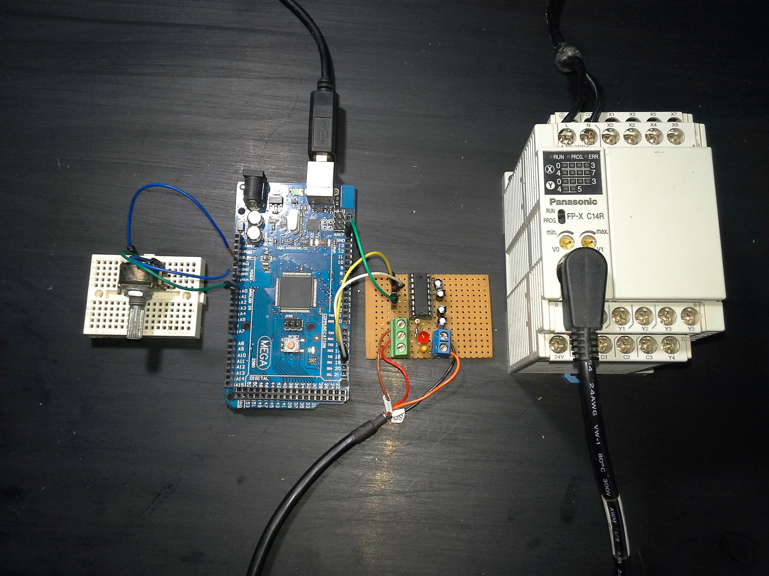
Components and materials required for testing
- Arduino MEGA 2560 R3
- MAX232 Converter
- Panasonic Industrial Equipment, PLC or HMI.
Mounting
Conclusions
In this case this frame has been created for a Panasonic PLC but with the skill 2 serial converters and the device in question and the documentation can generate the communication frame for any brand device either PLC or HMI.
Take into account WD_Mewtocol function, it works correctly, but it is still in test, but in case of finding some error.
The function only allows writing in registers. To read registers a new frame must be created that requests data from a specific register and the PLC will send the answer that must be interpreted in arduino.
With this example you will be able to write to any DT registers mainly from the Panasonic Fpx, FP0, FP0R, FP2, FP2SH and FPSigma PLC families among other existing families.
Currently Mew is being created for Arduino or ESP8266.
Easily this example that only writes in DT’S can be modified for writing other registers such as Relay R, and Y Outputs, WR and WY.
References
Downloads
Arduino IDE Code Arduino-Mewtocol-WriteArea