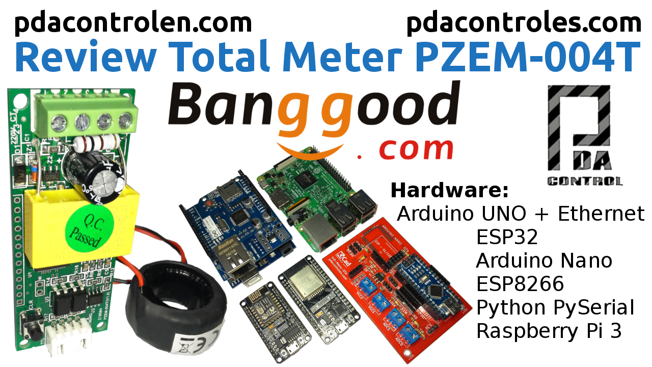
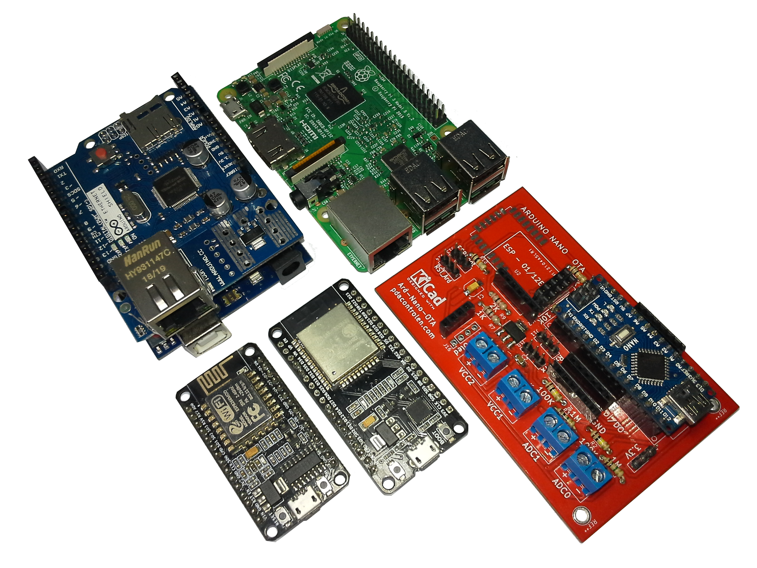
In this opportunity we will collect tests with my new electric consumption meter PZEM-004T, making integrations with some of the most known hardware platforms ESP8266, Arduino Nano, ESP32, Arduino UNO + Shield Ethernet W5100 and Python in Raspberry Pi.
For a long time I wanted to try the PZEM-004T of Peacefair, I bought my meter in the well-known Banggood.com Online store, at a very affordable price, it is impossible not to buy it.
![]()
This meter has great benefits in applications of measurement of residential electrical consumption at the DIY perfect for basic projects of analysis of electricity consumption at a low scale, perhaps at the residential level or home level and is perfect for integrations with IoT platforms, for example: Emoncms of the OpenEnergyMonitor Project.
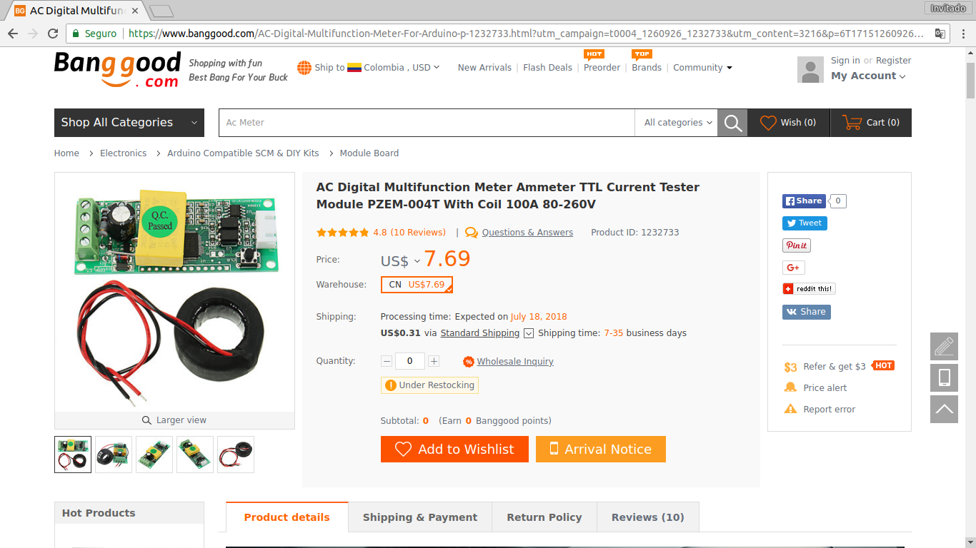
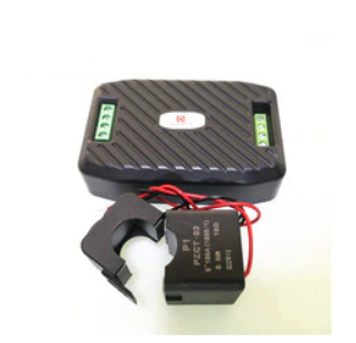
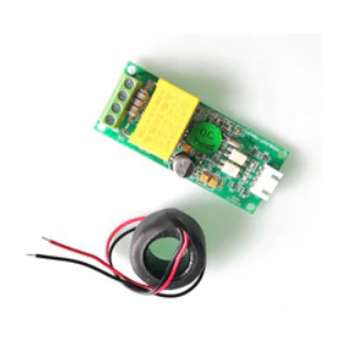
I placed my order at Banggood and after 7 days arrived my new meter and its respective CT or current transformer.

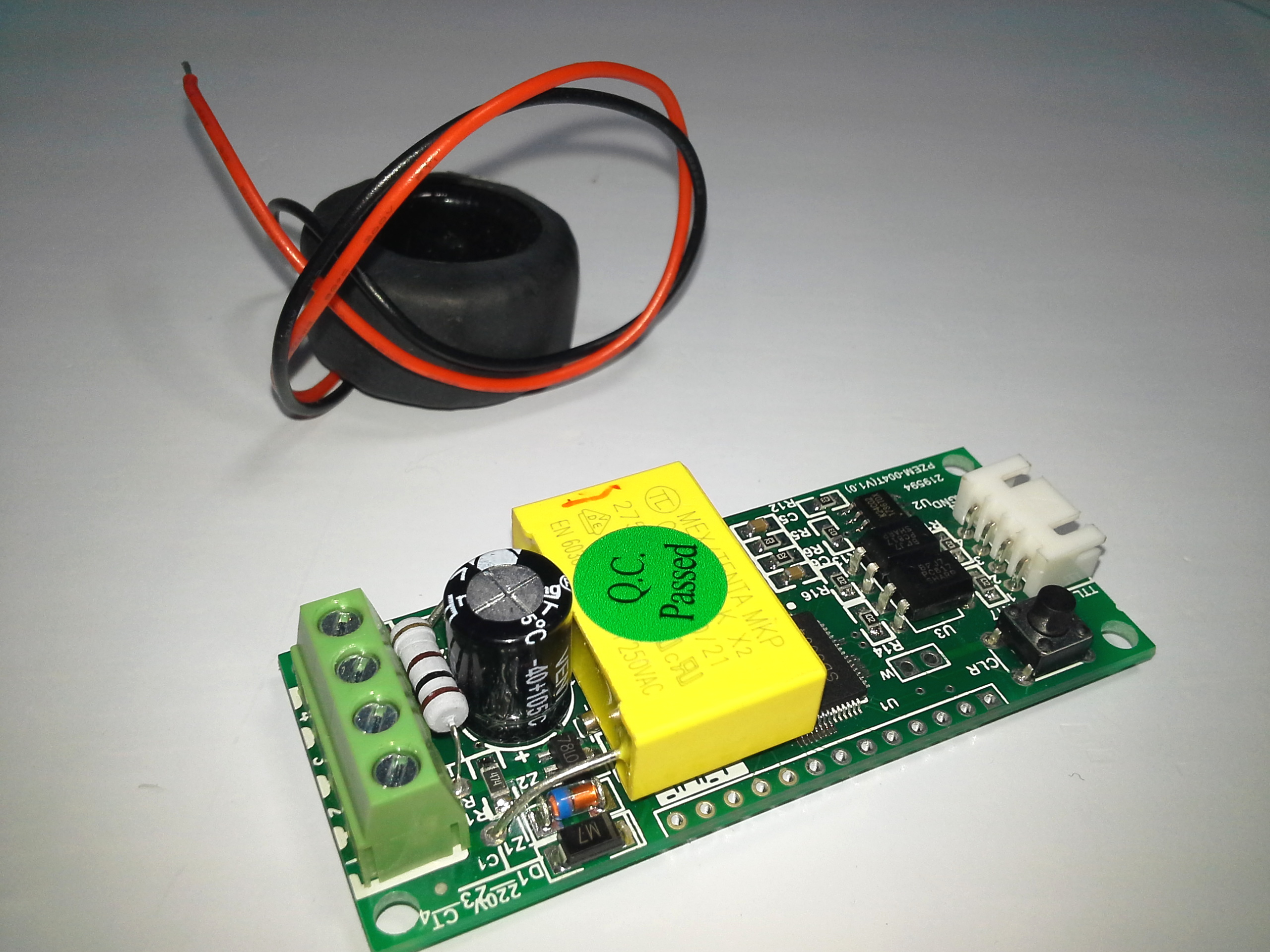
As mentioned before size is a great advantage, for low space projects, or small encapsulations.

PZEM-004T Meter
This version works exactly the same as the PZEM-004 version, its communication protocol is the same, it has the advantages of being a non-invasive meter in the electric circuit, the perfect size for small spaces, it has the 4 variables available Instantaneous Active Power “W”, Voltage “V”, Amperage “A” and Active Power Accumulated “Wh”.
Recommended Tutorial: Peacefair Power Meter PZEM 004 + ESP8266 & Arduino Nano
Warning: Caution is recommended since this project involves electrical risk or electrocution since 110 VAC – 120 VAC connected equipment is used, basic knowledge is required, please be previously documented in this regard.
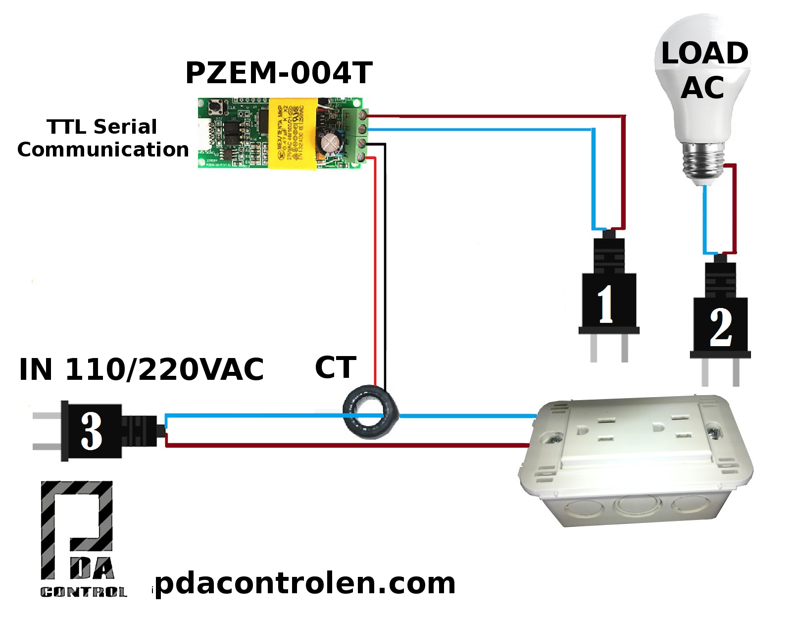
Connections
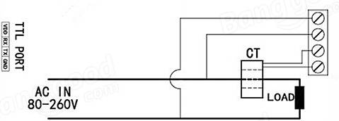
Test assembly
From previous tests I have been asked to share the electrical connection of the meter and the load, this is the connection used in my tests, this configuration is the same for the meters PZEM-004 and PZEM-004T.
Note: The plug 1 Meter power PZEM-004T, can be connected to the measuring point, or it is also connected to another point 110/220VAC from another part.
Warning: This assembly is for didactic tests, in case of making a real assembly take into account used cable gauge and knowledge of basic electricity.
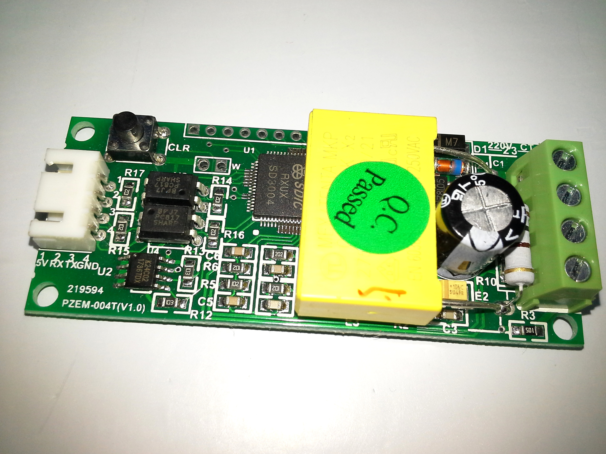
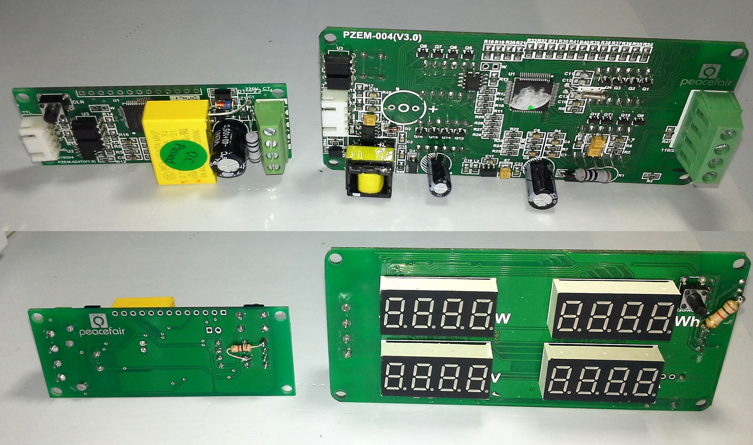
Front view
The main integrated SDIC SD3004 is the technically everything, Measurements, conversions, calculations and serial communication.
On the left below has another integrated 8-pin is an external I²C EEPROM memory that stores the kWh, in case of turning off the meter does not restart the accumulated, next to the white connector are the 2 optocouplers of isolation for serial communication.
CLR front push button. allows you to reset the accumulated kWh.
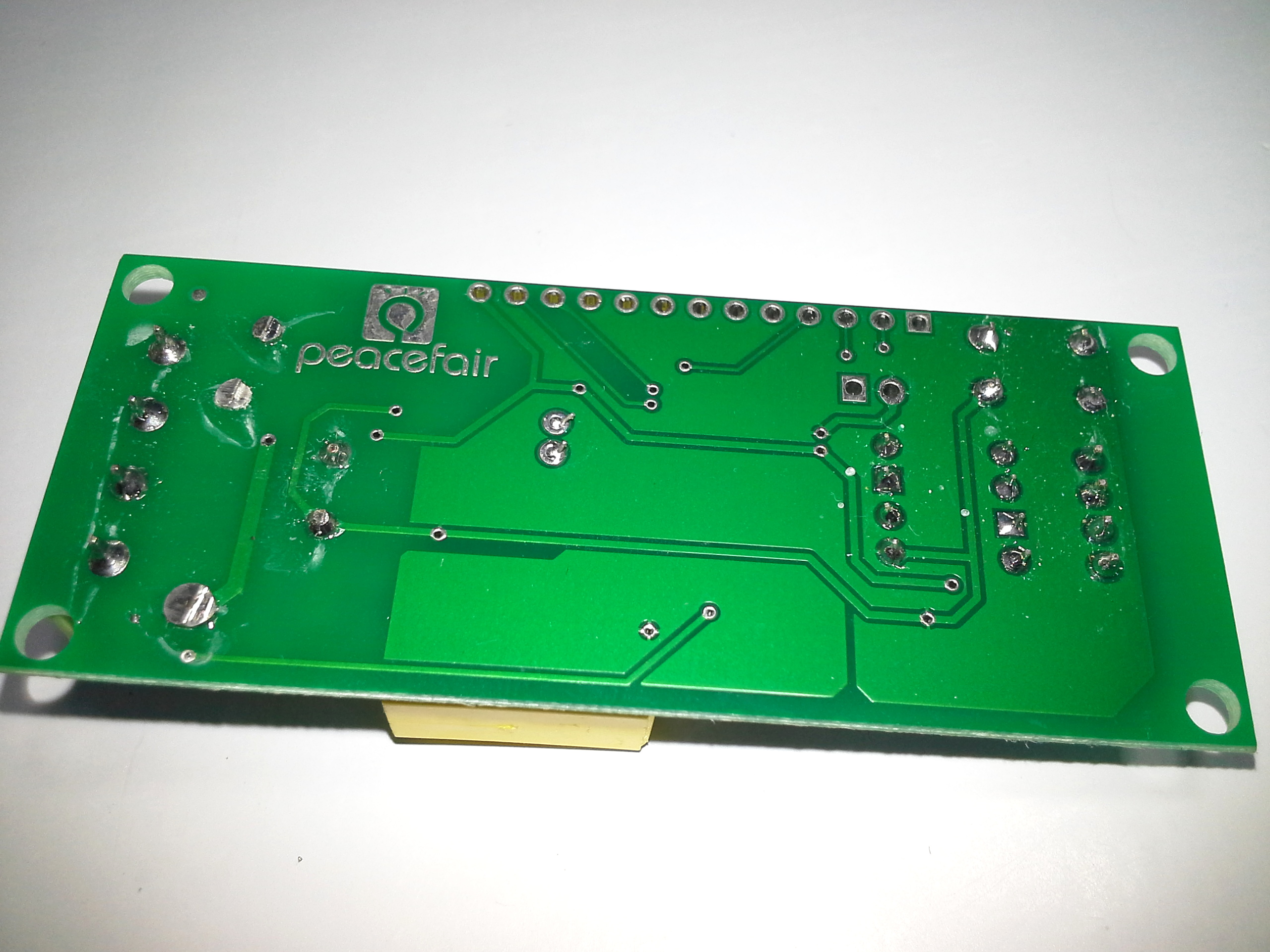
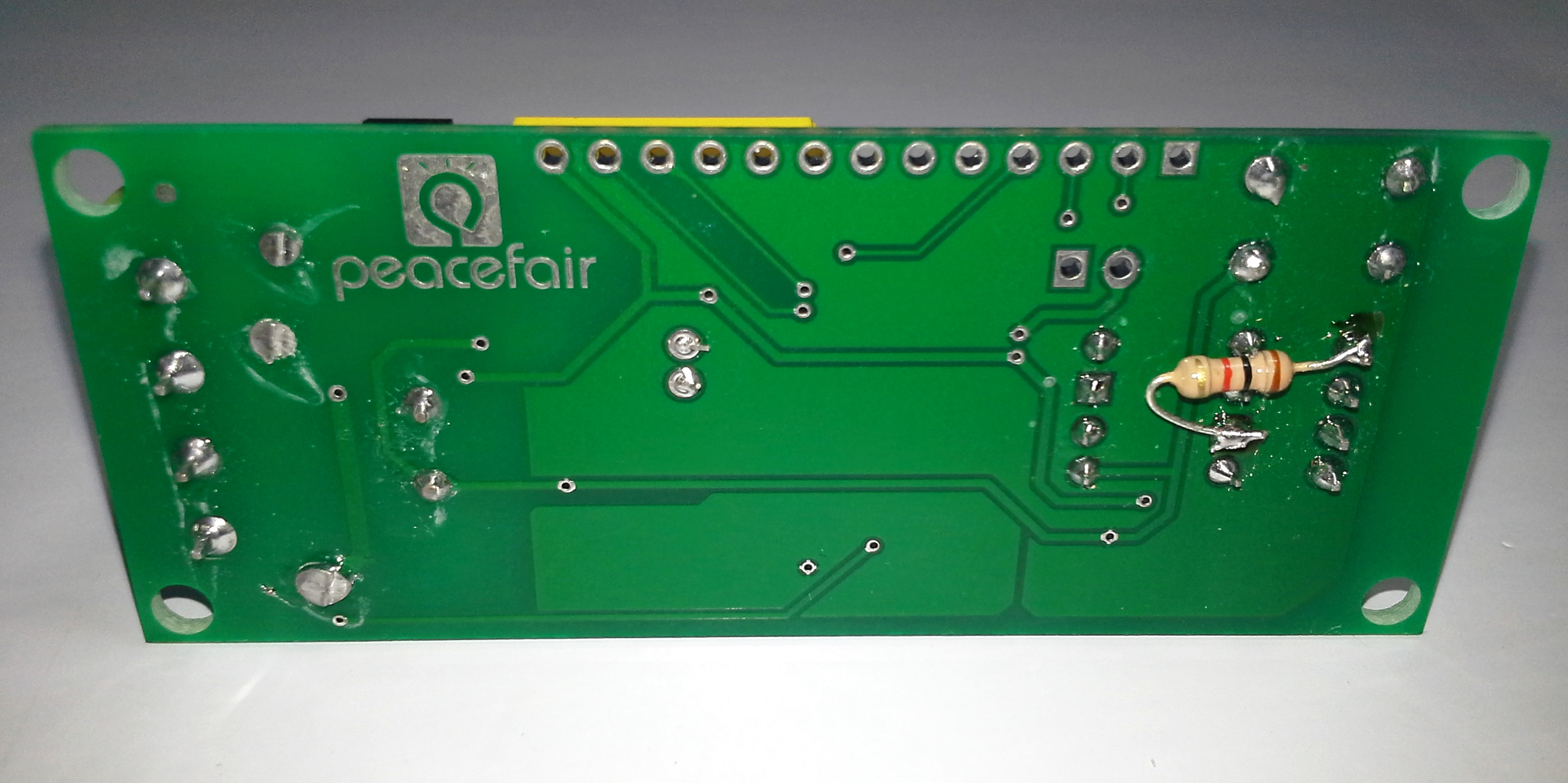
Back view
Modification TTL UART from 5v to 3.3v
This PZEM version has a Serial UART that works at 5V, will perform a modification welding a resistance of 1K to 1/4W to allow the communication to work at 3.3v in the case of plates such as Raspberry Pi, ES
P32 and esp8266, with this modification the UART will work at 5v or 3.3v.
Note: This is the simplest and most economical way if a TTL converter from 5 to 3.3v is not available, but it is not guaranteed to work in all cases and with all the meters, in my case it works without problems.
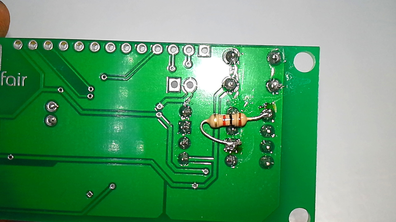
Modification Made
- The 1K resistance has been welded.
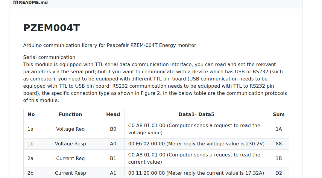
Library PZEM004T for Arduino IDE
There is a widely used library to communicate the Arduino and ESP8266 boards with the PZEM meters, available for Arduino IDE, a few months ago I noticed updates mainly compatibility with the ESP32.
This library was created by olehs, thank you for your great contribution.
Github : library PZEM004T.h
Comparative View PZEM-004T VS PZEM-004
Tests
This time we will perform 5 tests of our meter PZEM-004t, For this test I will use my soldering iron as AC charge, its consumption is approximately 25 Watts.
- Test PZEM-004t with ESP8266 12E NodeMCU
- Test PZEM-004t with Arduino Nano “Ard-Nano”
- Test PZEM-004t with ESP32 DEVKIT
- Test PZEM-004t with Arduino UNO + Shield Ethernet W5100
- Test PZEM-004t with Raspberry Pi 3 Model B using Python
Video: Complete Test
Review PZEM-004T with Arduino ESP32 ESP8266 Python & Raspberry Pi
1. Test PZEM-004t with ESP8266 12E NodeMCU
If you have read previous articles Peacefair Power Meter PZEM 004 + ESP8266 & Arduino Nano you may say that this test was already done, but this time the HardwareSerial library will be used instead of SoftwareSerial and we will use the second UART “serial port” of the ESP8266.
Materials and Where to Buy
- 1 PZEM-004T – Banggood
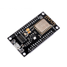
- 1 ESP8266 NodeMCU – Banggood
- 1 FTDI TTL to USB Serial Converter – Banggood
- 1 2N2907 PNP transistor TO-92 or similar PNP
- Jumper Wires Male-Female – Banggood
- Jumper Wires Male-Male – Banggood
- Jumper Wires Female-Female – Banggood
- 1 Breadboard 8.5 x 5.5cm 400 Points – Banggood
- Recommended: Download Banggppd AppTo get 10% off coupon
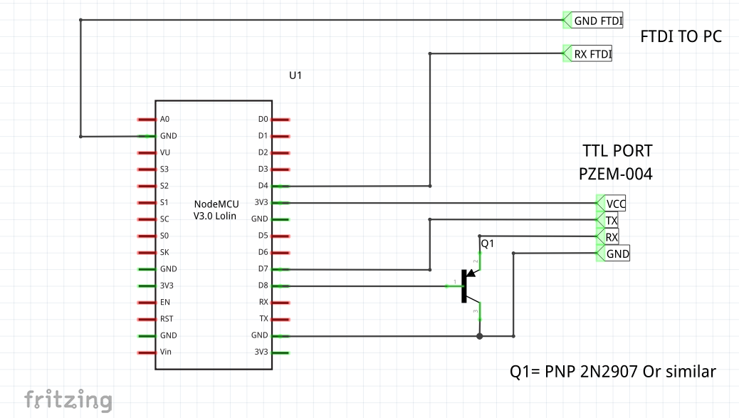
Connections
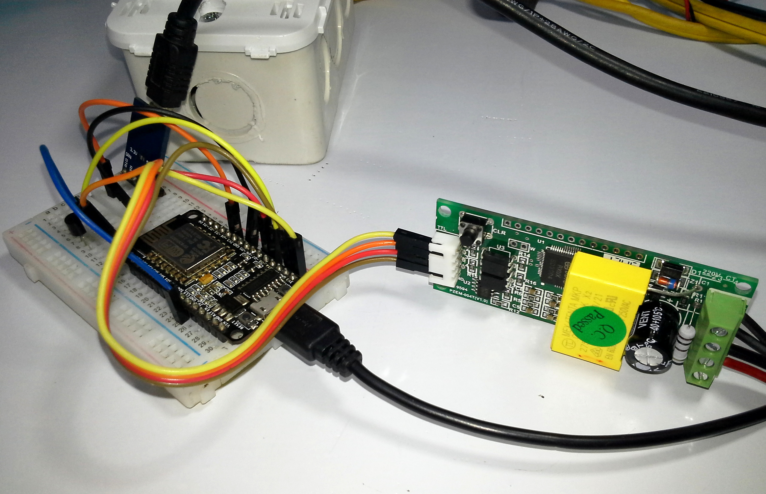
Mounting
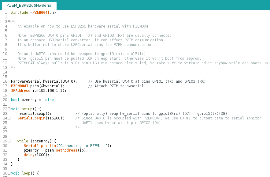
Arduino IDE Code
The main serial port or UART0 pins gpio01 (tx), gpio03 (rx) can not be used for debugging since it is busy communicating with the PZEM-004 Meter.
The PZEM meter is connected to the HardwareSerial port gpio13 (D7) (rx), gpio15 (D8) (tx), a PNP 2N2907 transistor is added in the gpio15 so that it is in low state when starting and/or programming the ESP8266.
Note: Without this transistor, the ESP8266 will not start when it is restarted and / or programmed.
The UART1 pin gpio02 (tx) has been used for serial debugging, since it is ttl a FTDI Converter is added to view from PC.
Note: Download links and/or github below.
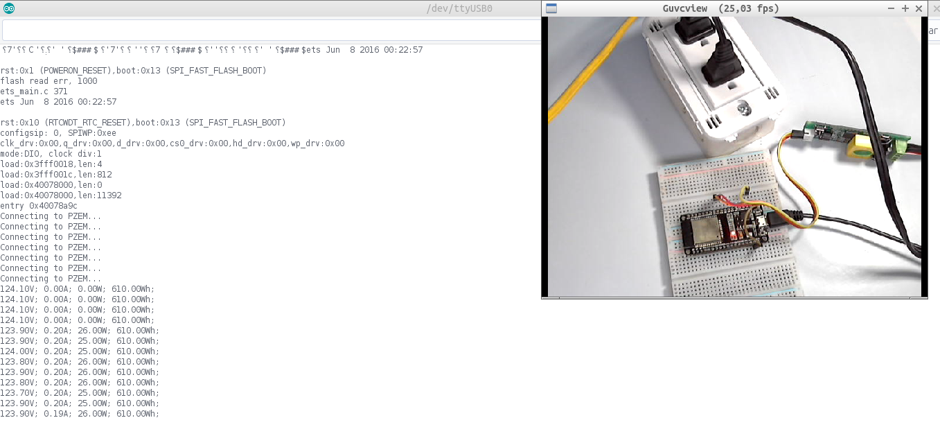
Serial Terminal
- Output port UART1 Serial1 (gpio2) TX D4, Requires Serial-USB FTDI converter.
Recommendation: For a more detailed explanation step by step I recommend watching the full video “Review PZEM-004T with Arduino ESP32 ESP8266 Python & Raspberry Pi : PDAControl” available on our PDAControl Youtube channel.
2. Test PZEM-004t with Arduino Nano “Ard-Nano”
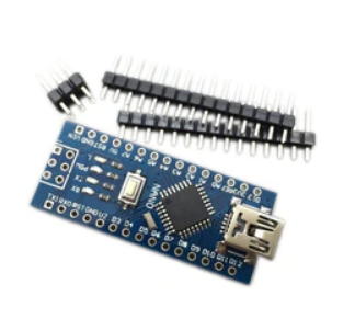
For communication with Arduino nano board, SoftwareSerial Library is used, I will also present one of my latest designs in KiCAD technically is a test board with Arduino Nano manufactured by the company PCBWAY, is for OTA programming with ESP8266 for next tests, but in this case we will only communicate the microcontroller with the meter.
Materials and Where to Buy
- 1 PZEM-004T – Banggood
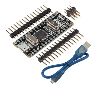
- 1 Arduino Nano v3 Clone – Banggood
- Jumper Wires Male-Female – Banggood
- Jumper Wires Male-Male – Banggood
- Jumper Wires Female-Female – Banggood
- 1 Breadboard 8.5 x 5.5cm 400 Points – Banggood
- 1 Shield / PCB Arduino-OTA V1.0 (Optional)
- Recommended: Download Banggppd AppTo get 10% off coupon
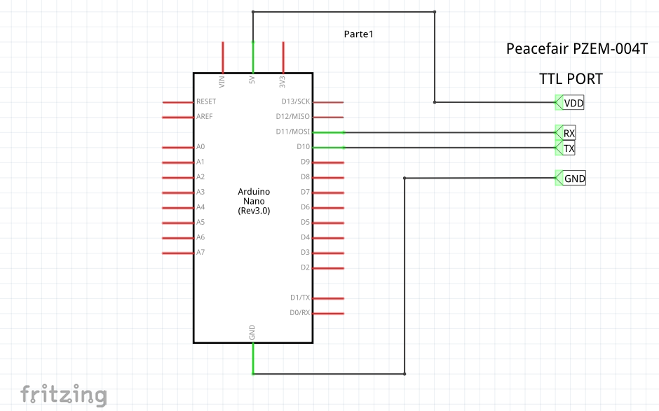
Connections
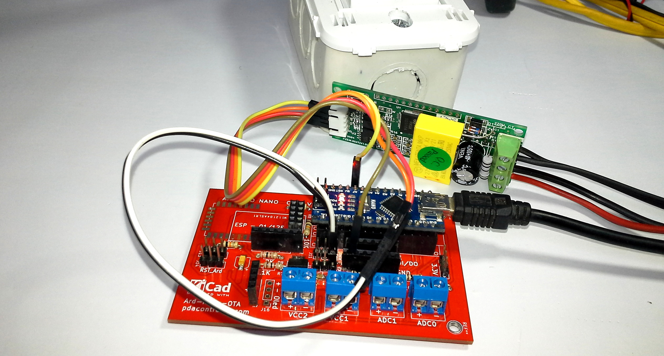
Mounting
- Ard-Nano-OTA Board Mount.
- Breadboard mounting.
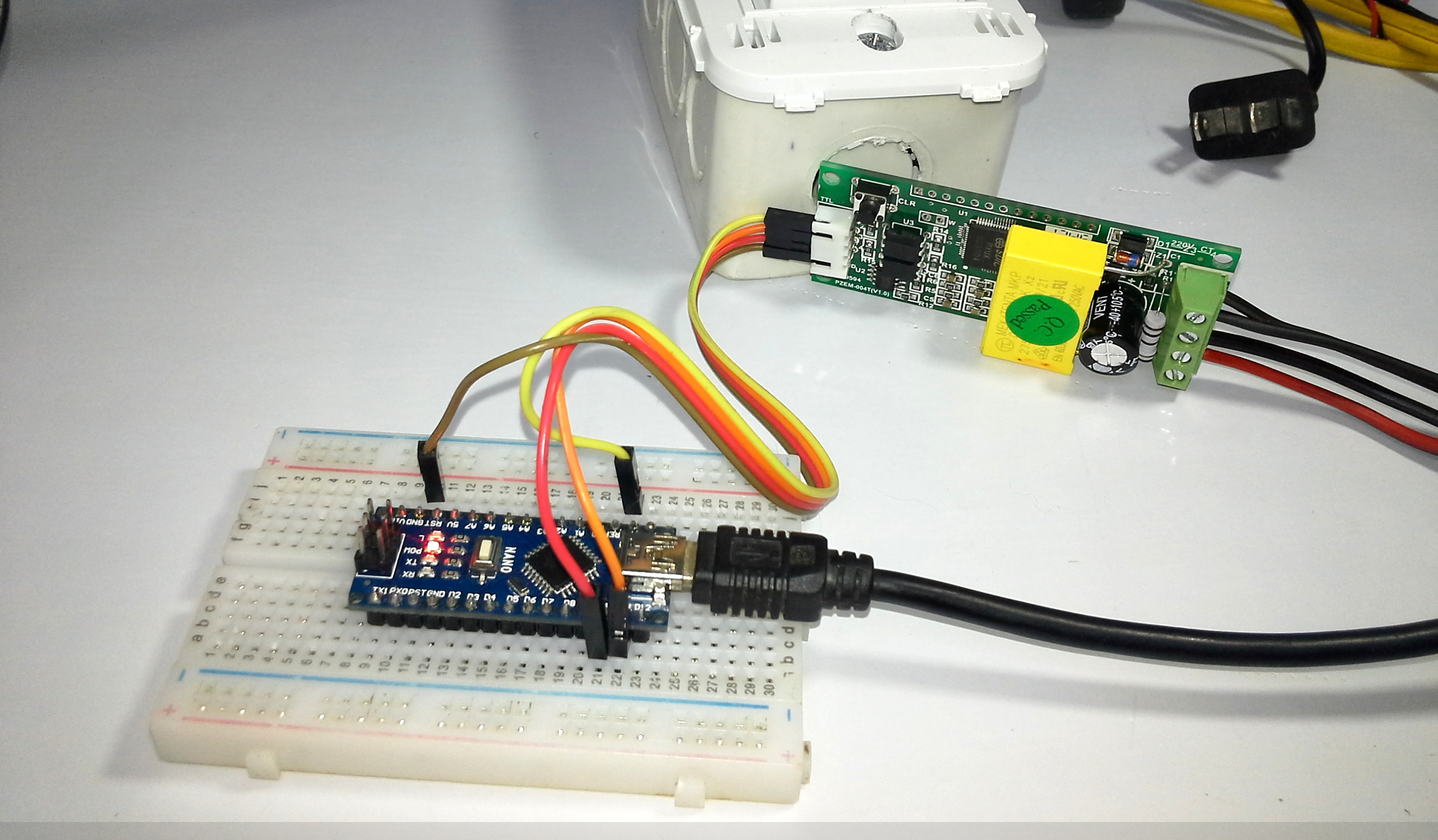
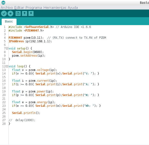
Arduino IDE Code
Pins 10 (rx) and 11 (tx) have been configured with SoftwareSerial for communication with the PZEM-004T meter.
Note: Download links and/or github below.
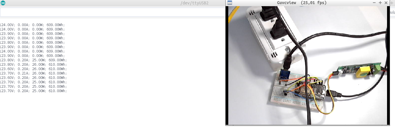
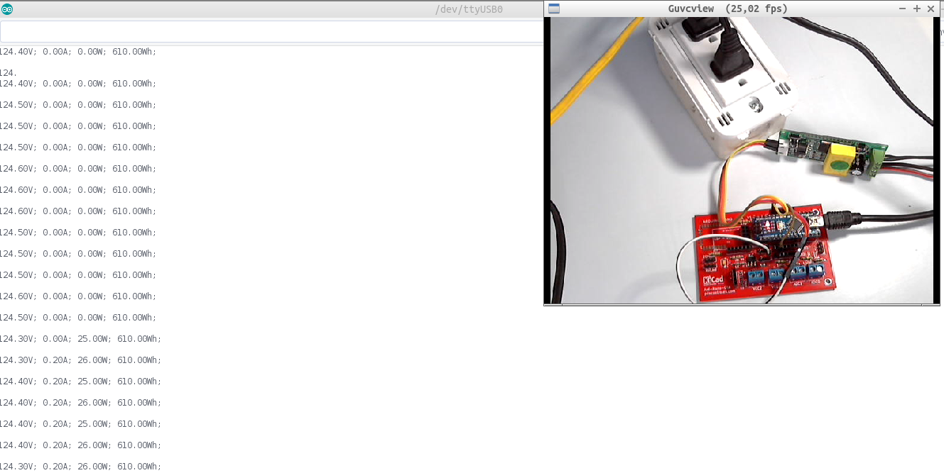
Serial Terminal
- Output port UART0 Serial0.
Recommendation: For a more detailed explanation step by step I recommend watching the full video “Review PZEM-004T with Arduino ESP32 ESP8266 Python & Raspberry Pi : PDAControl” available on our PDAControl Youtube channel.
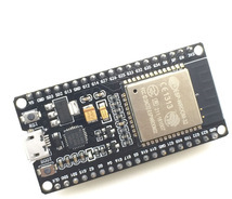
3. Test PZEM-004t with ESP32
This was one of the recent improvements to the PZEM-004T library allowing communication with an ESP32 module.
Materials and Where to Buy
- 1 PZEM-004T – Banggood
- 1 ESP32 DEVKIT V1 Doit – Banggood
- Jumper Wires Male-Female – Banggood
- Jumper Wires Male-Male – Banggood
- Jumper Wires Female-Female – Banggood
- 2 Breadboard 8.5 x 5.5cm 400 Points – Banggood
- Recommended: Download Banggppd AppTo get 10% off coupon
Connections
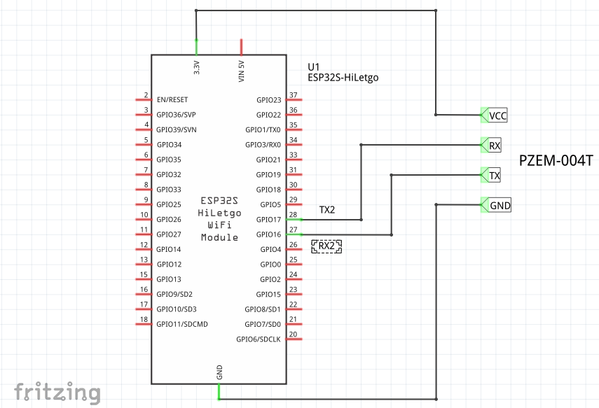
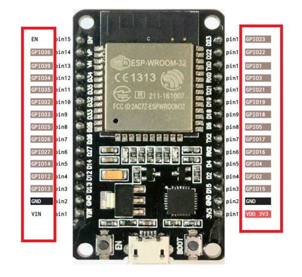
Distribution of Pins for ESP32
Recommendations validate pin location since it varies according to the module manufacturer, in my case I use an ESP32 DEVKIT V1 Doit module, I have found detailed documentation on variations of pin distribution in ESP32.
Recommended Tutorial : ESP32: INTERNAL DETAILS AND PINOUT.
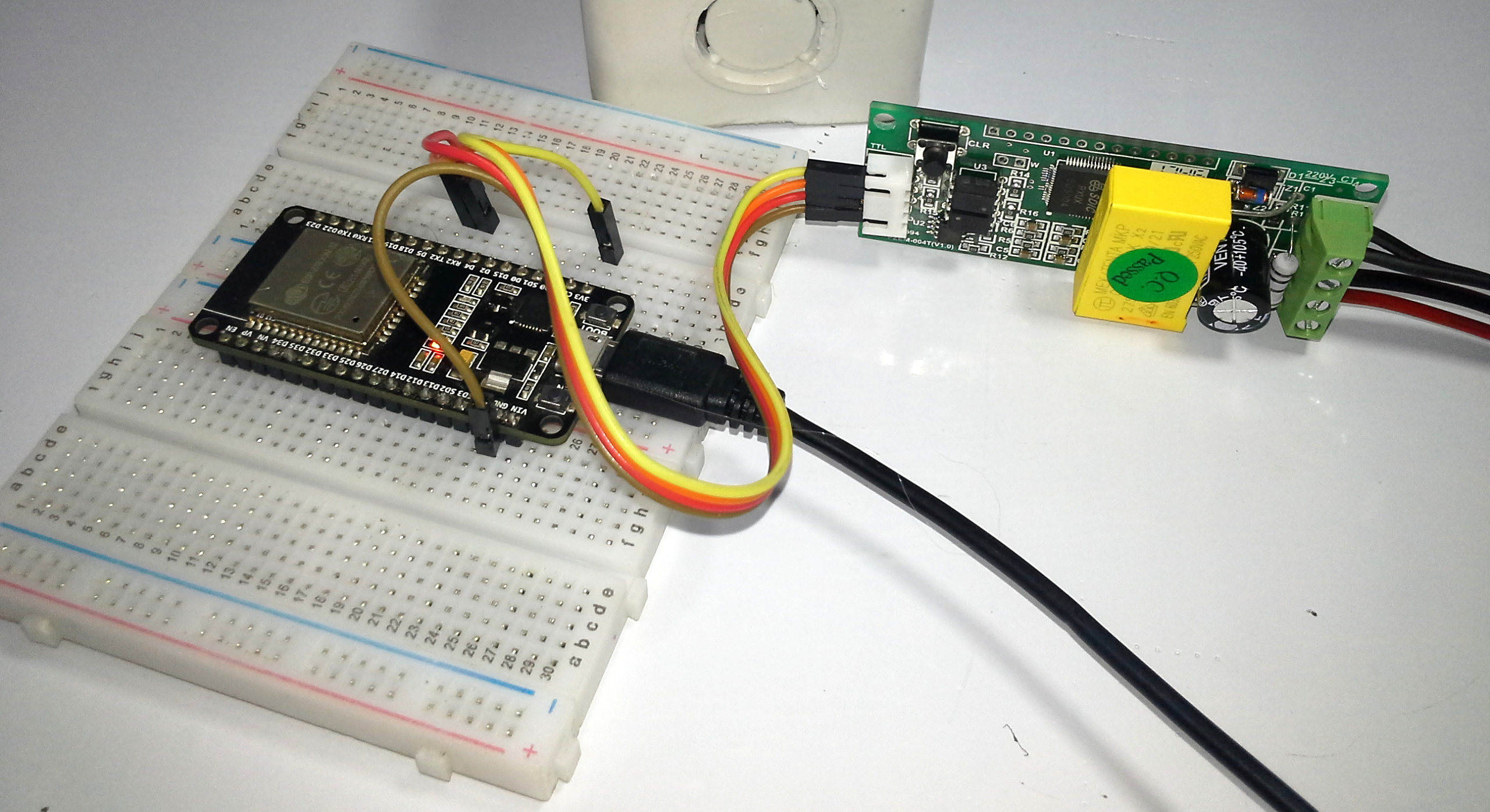
Mounting
Note: Given the design of the ESP32, for the assembly 2 Breadboard were used.
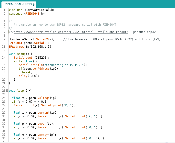
Arduino IDE Code
In this case the HardwareSerial library is also used, the communication is carried out by the pins of the UART2 IO-16 (rx2) and IO-17 (tx2).
Note: Download links and/or github below.
Serial Terminal
- Output port UART0 Serial0.
RECOMMENDED: Measurement Electrical consumption with Ubidots Industrial & ESP32 + PZEM-004T
Measurement Electrical consumption with Ubidots Industrial & ESP32 + PZEM-004T
Recommendation: For a more detailed explanation step by step I recommend watching the full video “Review PZEM-004T with Arduino ESP32 ESP8266 Python & Raspberry Pi : PDAControl” available on our PDAControl Youtube channel.
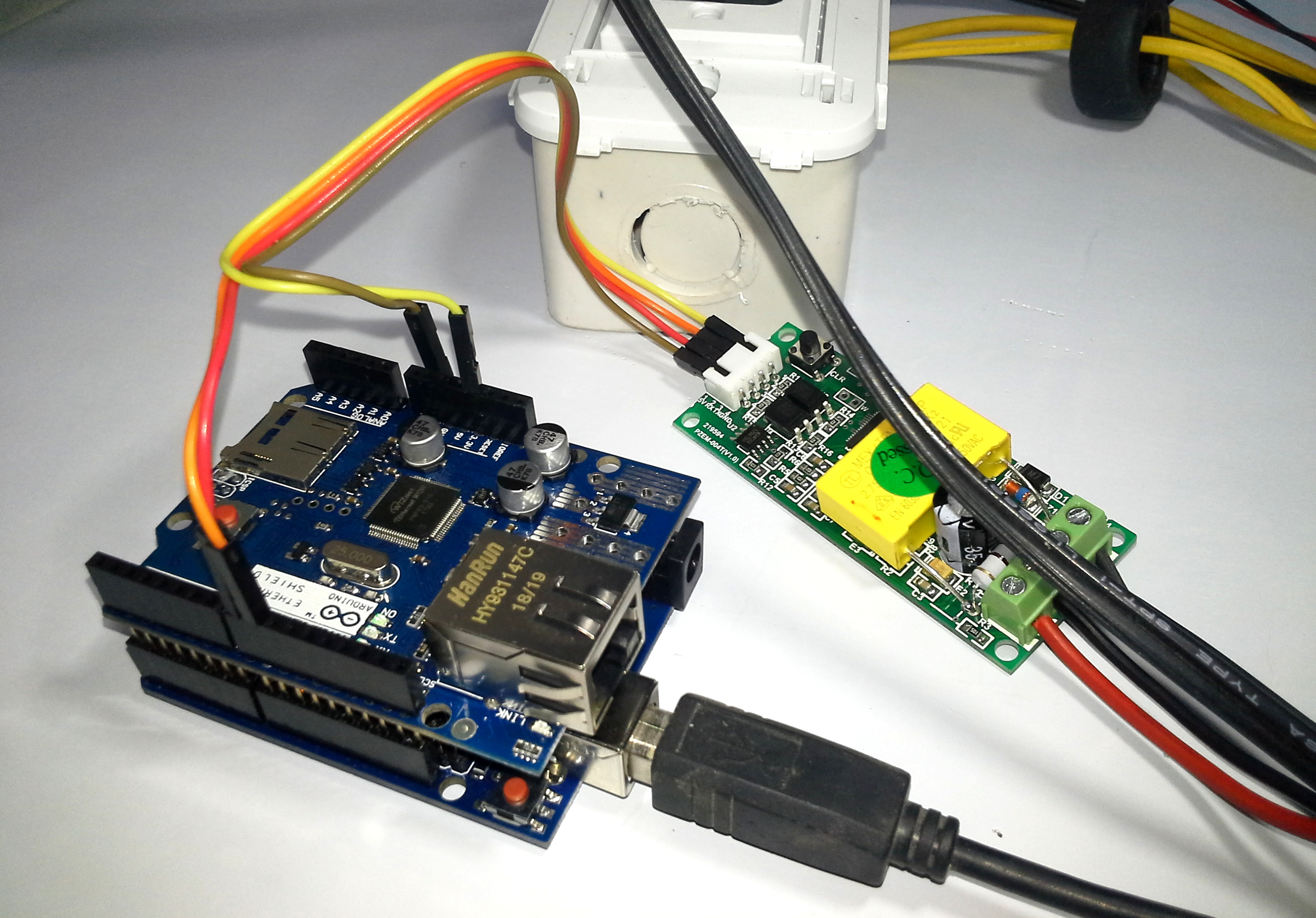
4. Prueba PZEM-004t con Arduino UNO + Shield Ethernet W5100
I was really a bit away from Arduino in my last tests, but I decided to buy and try one of the most famous or used plates, the Arduino UNO with the Shield Ethernet W5100 both were so cheap that it was impossible not to buy them.
Materials and Where to Buy
- 1 PZEM-004T – Banggood
- 1 Arduino UNO – Banggood
- 1 Shield Ethenet W5100 – Banggood
- Jumper Wires Male-Female – Banggood
- Jumper Wires Male-Male – Banggood
- Jumper Wires Female-Female – Banggood
- Recommended: Download Banggppd AppTo get 10% off coupon
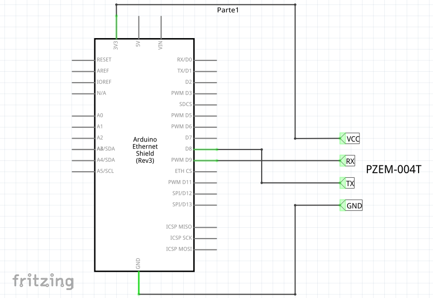
Connections
Mounting
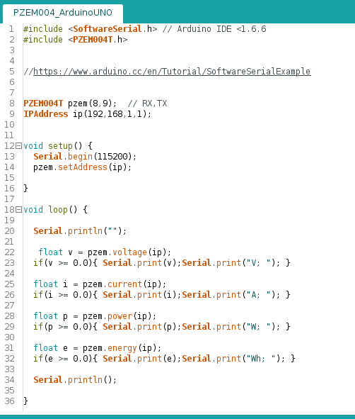
Arduino IDE Code
Although this case will not use the Ethernet Shield features such as LAN communication and microSD, it must be borne in mind that the Ethernet Shield works by SPI bus, which uses pins 10 and 11 of the Arduino UNO, for this reason and to avoid conflicts SoftwareSerial library that generates a new port to communicate with the PZEM-004T uses the rx (8) and tx (9) pins.
Note: Download links and/or github below.
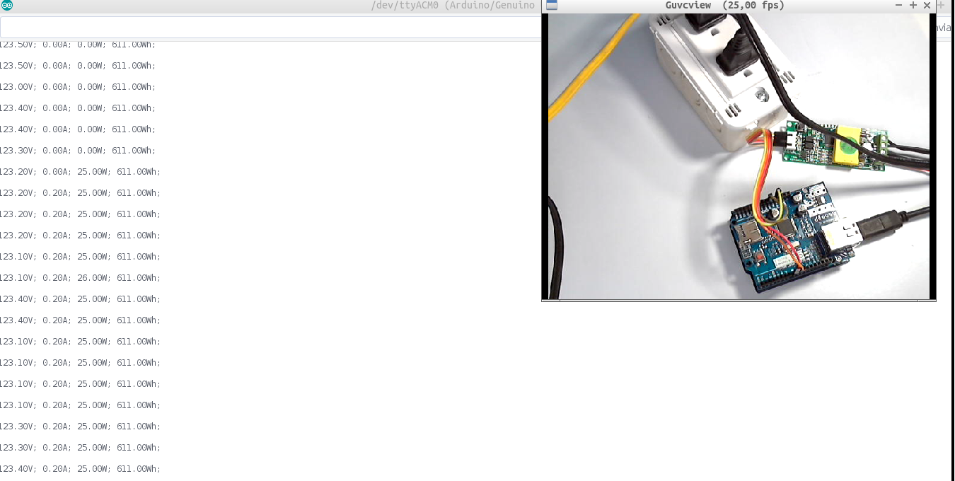
Serial Terminal
- Output port UART0 Serial0.
Recommendation: For a more detailed explanation step by step I recommend watching the full video “Review PZEM-004T with Arduino ESP32 ESP8266 Python & Raspberry Pi : PDAControl” available on our PDAControl Youtube channel.
5. Test PZEM-004t with Raspberry Pi 3 Model B using Python
 In this test maybe the most complex since a Raspberry Pi will be used, this test will be divided into 2 parts:
- Routine in Python for communication with PZEM-004T.
- Communication Raspberry Pi & Meter PZEM-004T isolated.
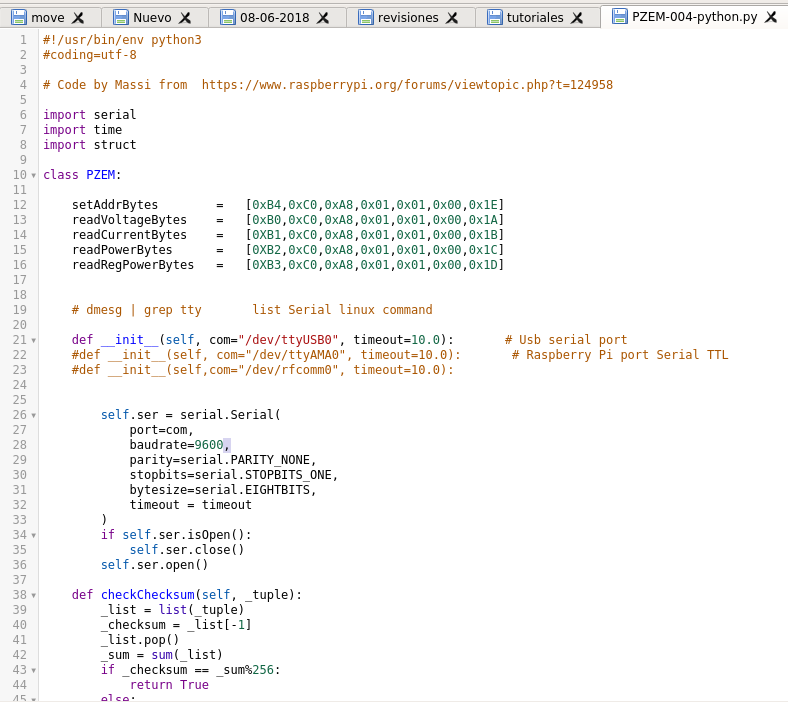
Python routine for communication with PZEM-004T
This very well structured routine, I found it in the Raspberrypi.org forum and apparently created by Massi, thanks to him for his contribution.
Source Code: Peaceview PZEM-004T Energy Module
Based on the code shared by Massi, the file PZEM-004-python.py has been created with the routine that we will execute in our Raspberry Pi to request data from our meter, make some modifications to the original code.
Note: Download links and/or github below.
Note: This file can be run on any computer running Python. example: WINDOWS, MacOS and LINUX, or any microcomputer that supports it, In this case we will test on a Raspberry Pi.
Recommendation: For a more detailed explanation step by step I recommend watching the full video “Review PZEM-004T with Arduino ESP32 ESP8266 Python & Raspberry Pi : PDAControl” available on our PDAControl Youtube channel.
Communication Raspberry Pi & Meter PZEM-004T isolated
A few weeks ago I have my Raspberry Pi 3, I have mounted the RASPBIAN STRETCH LITE version, without a desktop and I do the configurations remotely from an SSH client, I will not detail the process of mounting raspbian operating system since there are many tutorials in the network.
Recommended Tutorial: A look at the Raspberry Pi 3 Model B.
Materials and Where to Buy
- 1 PZEM-004T – Banggood
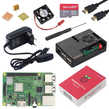
- 1 Raspberry Pi 3 Model B + Banggood
- 1 FTDI TTL to USB Serial Converter – Banggood
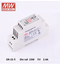
- 1 Power Supply 5V 2A – Banggood
- Jumper Wires Male-Female – Banggood
- Jumper Wires Male-Male – Banggood
- Jumper Wires Female-Female – Banggood
- 1 MicroSD 8GB Card with Raspbian OS Installed
- Recommended: Download Banggppd AppTo get 10% off coupon
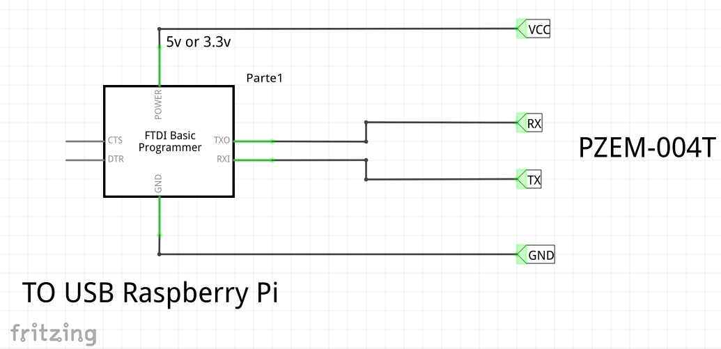
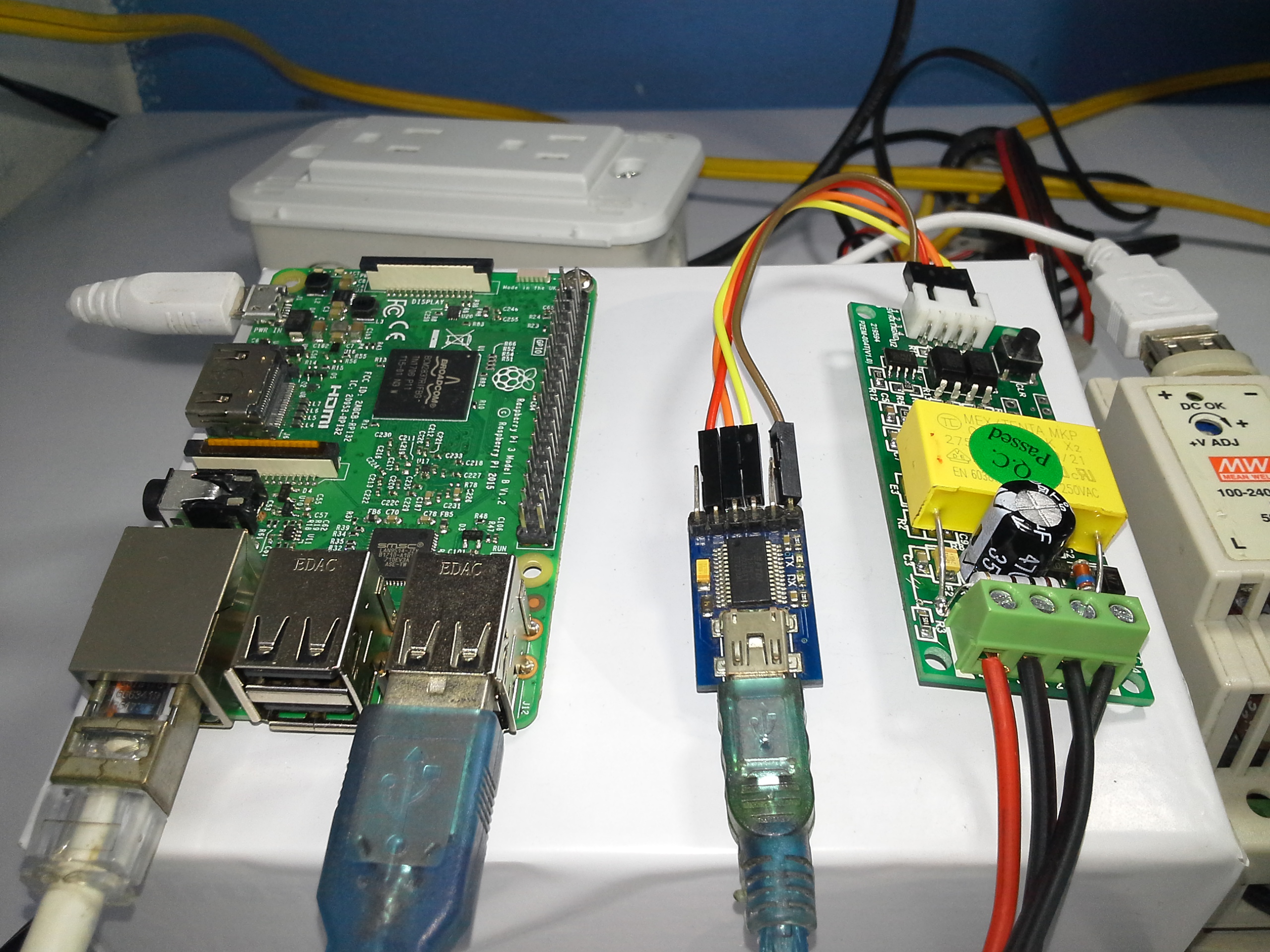
Connections
Connect the FTDI converter to any of the available USB ports of our Raspberry Pi, the TTL connection between FTDI and PZEM-004T Meter.
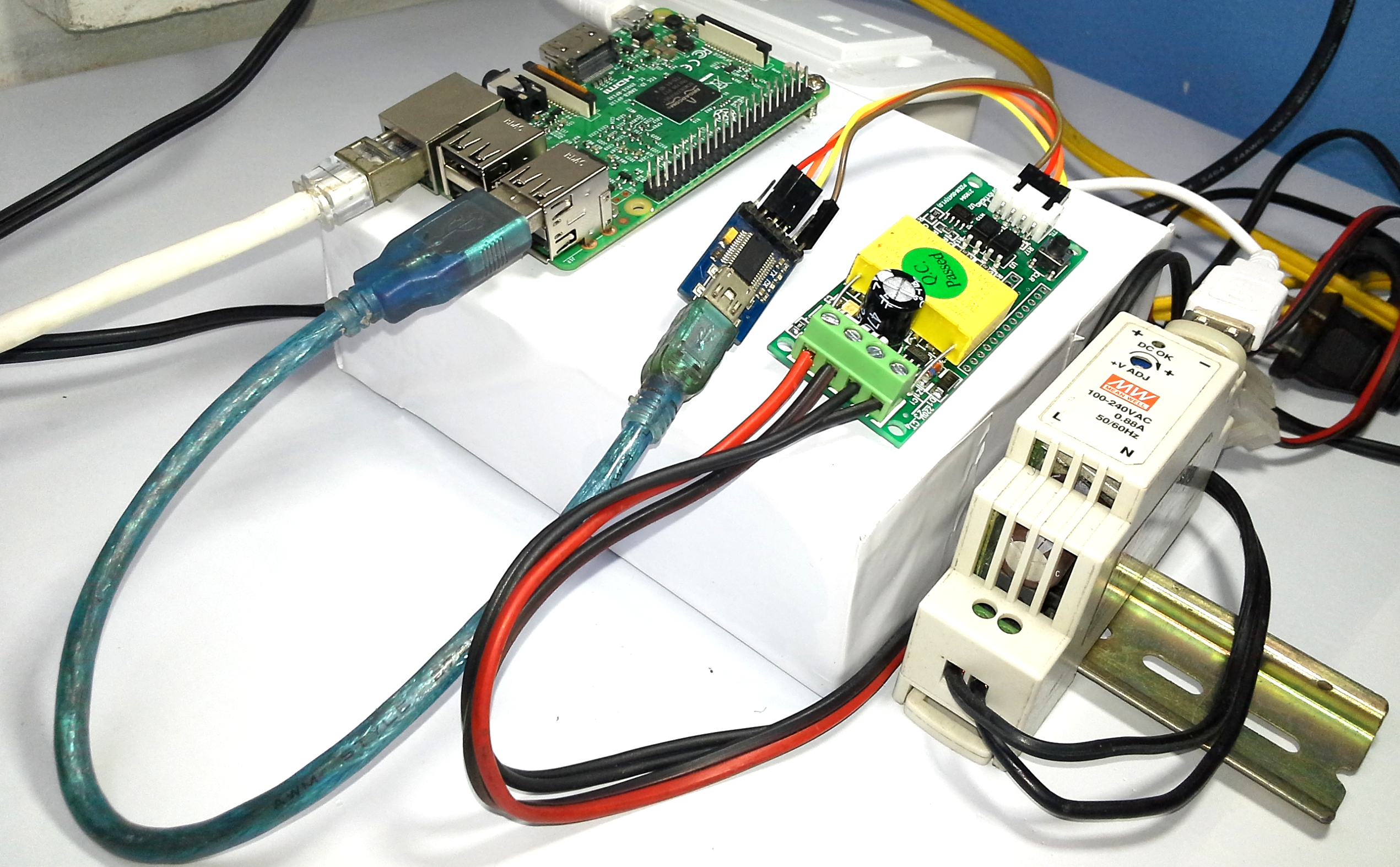
Mounting
In case I use a FTDI Serial USB Converter as an interface between the Raspberry Pi and the PZEM-004T Meter, I prefer to use this method of isolation, perhaps the most obvious thing for some is to directly use the serial port of Raspberry Pi, but I personally do not like it use the gpio’s only if it is extremely necessary, but I will reserve it for future tests.
IMPORTANT: It is recommended for the Raspberry Pi a power supply of 5v to 2A, minimum 1A, without connecting any peripheral to the USB or its GPIO’s.
Below I will detail step by step how to request data from the PZEM-004T meter with a Raspberry Pi:
- Having Raspberry Pi ready with Raspian OS installed and SSH client installed, I recommend RASPBIAN STRETCH LITE version.
- Connect Raspberry Pi to the local network (Router / Switch), by wire ethernet or Wifi.
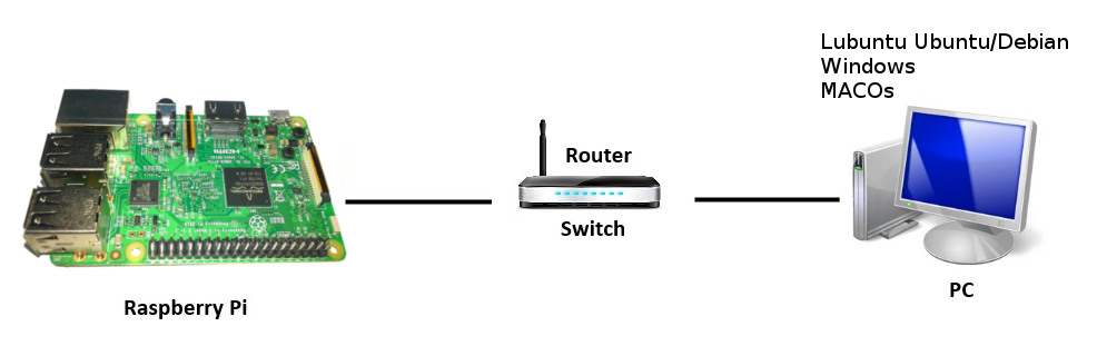
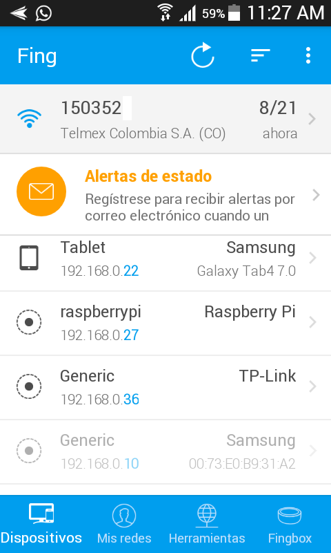
- Know the IP address assigned to our Raspberry Pi, I recommend using FING App to see addresses of devices in local network, in my case my Raspberry pi has the address 192.168.0.27, as it is DHCP could change depending on the configuration of your router.
Recommended Tutorial: How to find IP addresses of Ethernet devices with FING App?
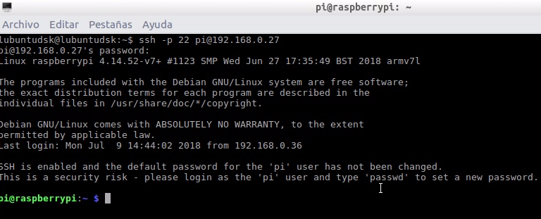
- Connecting with Raspberry Pi from SSH client Linux, you can also use Putty in case of using Windows or MacOS:
- in my case Linux Lubuntu (Ubuntu / Debian), Open command terminal and connect to RPi with the address of the device.
ssh -p 22 pi@192.168.0.27
User: pi
We already entered the terminal of our Raspberry Pi Remotely, from here we have total control of our Raspberry Pi.
Recommendation: For a more detailed explanation step by step I recommend watching the full video “Review PZEM-004T with Arduino ESP32 ESP8266 Python & Raspberry Pi : PDAControl” available on our PDAControl Youtube channel.
Create folder “python-utilities” in Raspberry Pi to save file “PZEM-004-python.py”.
mkdir python-utilities
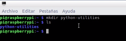
- enter folder “python-utilities”
cd..
- Locate file “PZEM-004-python.py” on our PC, in my case Lubuntu the path /home/lubuntudsk, for Windows and MacOS users is the current user folder, ready to move file to RPi.
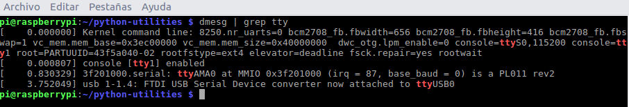
- List serial ports of Raspberry Pi, search FTDI USB Serial in my case dev/ttyUSB0
-
dmesg | grep tty
- Edit serial port in file “PZEM-004-python.py”, enable line 21 for communication with port com=”/dev/ttyUSB0″ as the case may be.

def __init__(self, com="/dev/ttyUSB0", timeout=10.0): # Usb serial port
- Open new command terminal on our PC.
- Move file “PZEM-004-python.py” from PC to Raspberry Pi, we will use the scp protocol “Simple Communication Protocol” is a method of transferring files using SSH. File name to move, SSH RPi connection and destination location is required, I recommend not using spaces in the names of the files.
scp PZEM-004-python.py pi@192.168.0.27:~/python-utilities
File moved correctly from PC with Lubuntu to Raspberry Pi

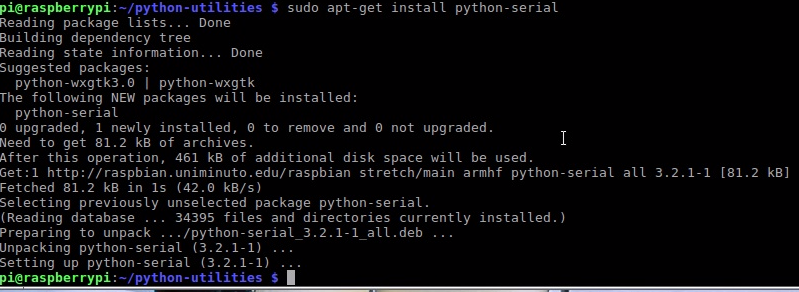
- By default Raspbian OS has Python installed, but does not have the PySerial library for serial communication, we will install it with the following command.
sudo apt-get install python-serial
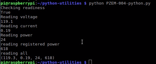
- Execute file “PZEM-004-python.py” to request data to PZEM-004T.
python PZEM-004-python.py
If it is executed and the connections are correct, the following will be displayed, communicating successfully.
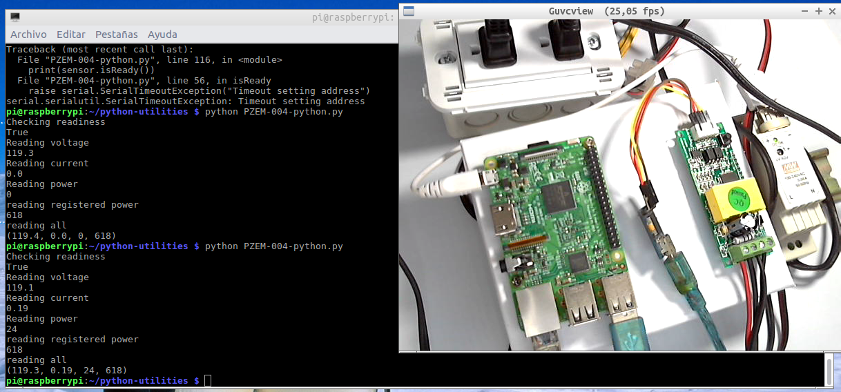
- In case of communication failure with meter, a Timeout exception will be displayed when not receiving a response through the Serial in 10 seconds, verify rx / tx connections.
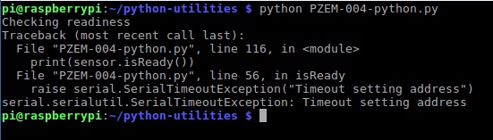
Recommendation: For a more detailed explanation step by step I recommend watching the full video “Review PZEM-004T with Arduino ESP32 ESP8266 Python & Raspberry Pi : PDAControl” available on our PDAControl Youtube channel.
Conclusions and General Considerations
Initially, a lot of caution should be taken since this project involves electrical risk or electrocution since 110VAC -120 VAC is used, although some do not consider it high voltage, this does not minimize the danger, it is recommended to have basic knowledge or documentation, never make connections When hot, always de-energize the power circuits.
Because I have no idea of your technical skill level or the requirements of your country’s laws in terms of electricity supply, etc., I do not accept any responsibility for any damage caused through the following advice on these pages. When it comes to network stresses, you should make sure everything you are doing is safe and, if you are not sure, ask for the advice of someone who is safe.
The meter PZEM 004T, is very practical, very basic and its low price meets good performance, I do not recommend it for industrial applications taking into account the environment, but I leave its applicability at your discretion, your point of measurement of VAC is the Same power point, allowing measurements between 80-260VAC.
Perhaps the only detail point in the meter is that it is not known how much it is turned on since it has no indicator, but it is not a serious inconvenience for its operation in general.
Thanks to …
Thanks to the Banggood online store.
Thanks to olehs creator of the library PZEM004T.h
Thanks to Massi for the Python-PZEM00T routine.
Conclusions and Considerations by test
Test PZEM-004t with ESP8266 12E NodeMCU
Apparently although the serial connection of the PZEM-00T is made with the NodeMCU by the pin pins gpio13 (D7) (rx), gpio15 (D8) (tx), the main port UART0 is busy communicating with the meter, technically the HardwareSerial library internally directs the PZEM frame internally from UART0 to D7 and D8, for this reason the pin UART1 Serial1 (gpio2) D4 is used for debugging adding an FTDI.
Test PZEM-004t with Arduino Nano “Ard-Nano”
The all Arduino boards, the favorite Nano, small and has everything, does not present any inconvenience with the meter.
A few days ago I made the design of a shield or trainer for my Arduino Nano, I designed my PCB’s with the company PCBWAY, this prototype “Arduino-OTA” is for future tests, for the possibility of programming the arduino board wirelessly with 2 modules ESP8266 very easy.
Test PZEM-004t with ESP32 DEVKIT
The communication ESP32 and PZEM-004T worked without problems, perhaps the only drawback is locating the appropriate pinout for the ESP32 modules since there are a large number of manufacturers and the distribution of pins may vary.
Test PZEM-004t with Arduino UNO + Shield Ethernet W5100
Although for our tests I usually use ESP8266 almost always, I did not have an Arduino UNO and I had always been curious to try the W5100 Ethernet Shield and also because of several comments they suggested that I include it in my tests.
Test PZEM-004t with Raspberry Pi 3 Model B using Python
Really of the 5 tests made this is obviously the most demanding, since it requires basic knowledge in Linux, file management through command line, know a little about SSH protocol and obviously know a bit about Python, I hope that this tutorial will serve as introduction to people without knowledge and can do it without problems.
Since the Raspberry Pi is a mini-computer that runs an Operating System, it must be very careful in its handling, it is very different from a micro-controller which predominates in previous tests.
WARNING: Always turn off the Raspberry Pi by command terminal “sudo poweroff” to avoid damaging the operating system and lose everything.
sudo poweroff
Currently the Raspberry Pi is globally recognized and there are plenty of tutorials on how to assemble your Raspbian operating system, I recommend using the version without desktop or graphics to optimize overall operation.
In the tutorial we tried to explain how to make the movement of files from a computer to our mini-computer and how to execute our Python file.
Regarding Python, I have always said it and I will say it, it is the language par excellence for practical, basic and fast applications. In this case, a protocol has been created in a simple file.
Finally for the test I decided not to connect the PZEM-004T directly to the UART of the Raspberry Pi located in its gpio’s, keep in mind if using this UART it works at 3.3v for greater security, to use the file “PZEM-004-python.py” technically only the serial port should be modified by the UART “/dev/ttyAMA0” own Raspberry Pi.
Comment line 21 and enable 22:
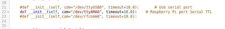
#def __init__(self, com="/dev/ttyAMA0", timeout=10.0): # Raspberry Pi port Serial TTL
Downloads / Github
- Github : library PZEM004T.h
- Complete Project Github: Test Meter PZEM-004T with Arduino ESP32 ESP8266 Python & Raspberry Pi
- Github: Test Meter PZEM-004T with Arduino Nano
- Github: Test Meter PZEM-004T with Arduino UNO + Shield Ethenet W5100
- Github: Test Meter PZEM-004T with ESP32
- Github: Test Meter PZEM-004T with ESP8266
- Github. Test Meter PZEM-004T with Python On Raspberry Pi 3
This is a great site! Thank you for putting it together. I tried to follow your instructions under “Test PZEM-004t with ESP8266 12E NodeMCU”. I purchased two PZEM-004T-100A V3 but can’t them to work. I soldered the 1KOhm resistor on the V3 PZEM as displayed on this picture https://user-images.githubusercontent.com/34340210/63591794-cf3d5d80-c57d-11e9-9945-eb062bebf71b.jpeg withour success. I have the wiring correct and I am using the 2N2907 PNP transistor. It seems the ESP does not manage to connect to the PZEM as the Serial on the FTDI keeps looping on “Connecting to PZEM…” I tried with with two different ESP, PZEM and PNP transistors. Would you have any clue?