This time the test will be performed on the well-known Adafruit.IO platform.
What is Adafruit.IO? It is a solution for the construction of applications IoT created by Adafruit Industries, the well-known open-source hardware marketer, have created this platform for the internet of things based on platforms known as Arduino, Raspberry pi, ESP8266, Intel Galileo, Serial devices And Wifi among others. The Communication API is based on MQTT client with Adafruit servers. In a few minutes you can create a high quality dashboard.
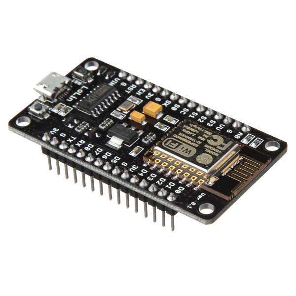
In this case we will perform the Tests with Module ESP8266 in the following tutorial we will indicate step by step installations and configurations for tests with the platform Adafruit.IO.
Official website: io.adafruit.com
Official website: adafruit.com
Tutorial Platform IoT Adafruit.IO & ESP8266 12E Part 1/2
- Quick introduction to Adafruit.IO
- Create account at Adafruit.IO
- Download libraries and examples
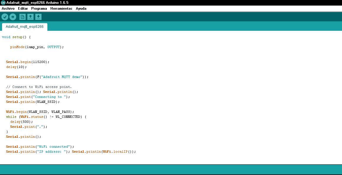
- Revision of Arduino IDE code
Arduino IDE
To do the test we have taken 2 examples of github and an example has been created that performs the reading of (LDR) and control of (GPIO 04) using the protocol MQTT, since none of the examples performed both functions is created example Download available below, it is required to have the AIO-KEY and in Username.
Full Downloads Bottom …
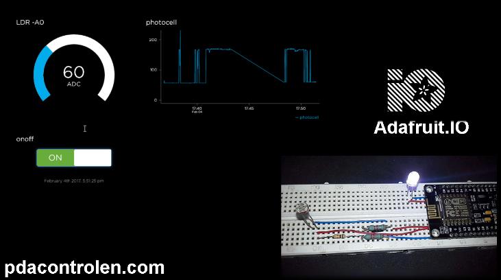
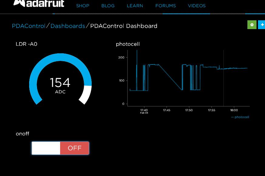
Dashboard Adafruit.IO
The Arduino code, generates the Feed “photocell” associated with the LDR that performs the reading to the ADC0.
The “onoff” feed must be created on the platform in the Feeds tab, the “onoff” feed is assigned the on / off control of the led diode assigned to the GPIO04.
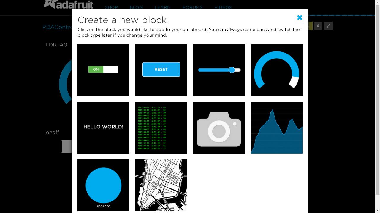
Widgets Available
The following widgets have been assigned:
- Toggle: for the control of the GPIO (Led), sends the Strings “ON” – “OFF” to the ESP8266 module.
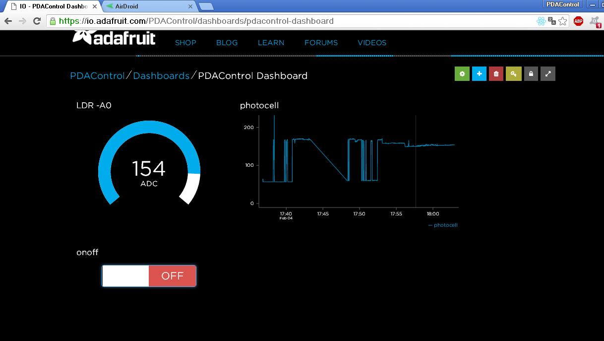
- Gauge: Allows the display of the value of the ADC0, configured from 0 to 200 given the configuration and conditioning of the ADC.
- Chart Line: Graph the value of the ADC0.
Dashboard Online
Tutorial Platform IoT Adafruit.IO & ESP8266 12E Part 2/2
- Download Arduino IDE code, example Adafruit_MQTT_esp8266.
- Dashboard Settings.
- Connection test ESP8266 and Adafruit.IO.
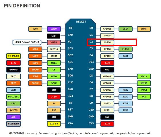
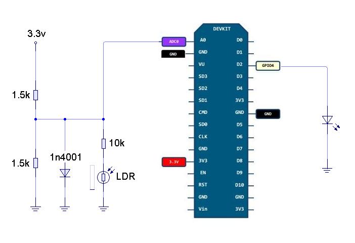
Pinout ESP8266 12E NodeMCU
Materials
1 LDR (Photoresistance)
2 Resistors of 1.5K
1 Diode 1N4001
Connections
Note: In this case the LDR for safety never exceeds 500mV to avoid damaging the ADC0, MAX 1.0V adc0.
- Resistors are Precision.
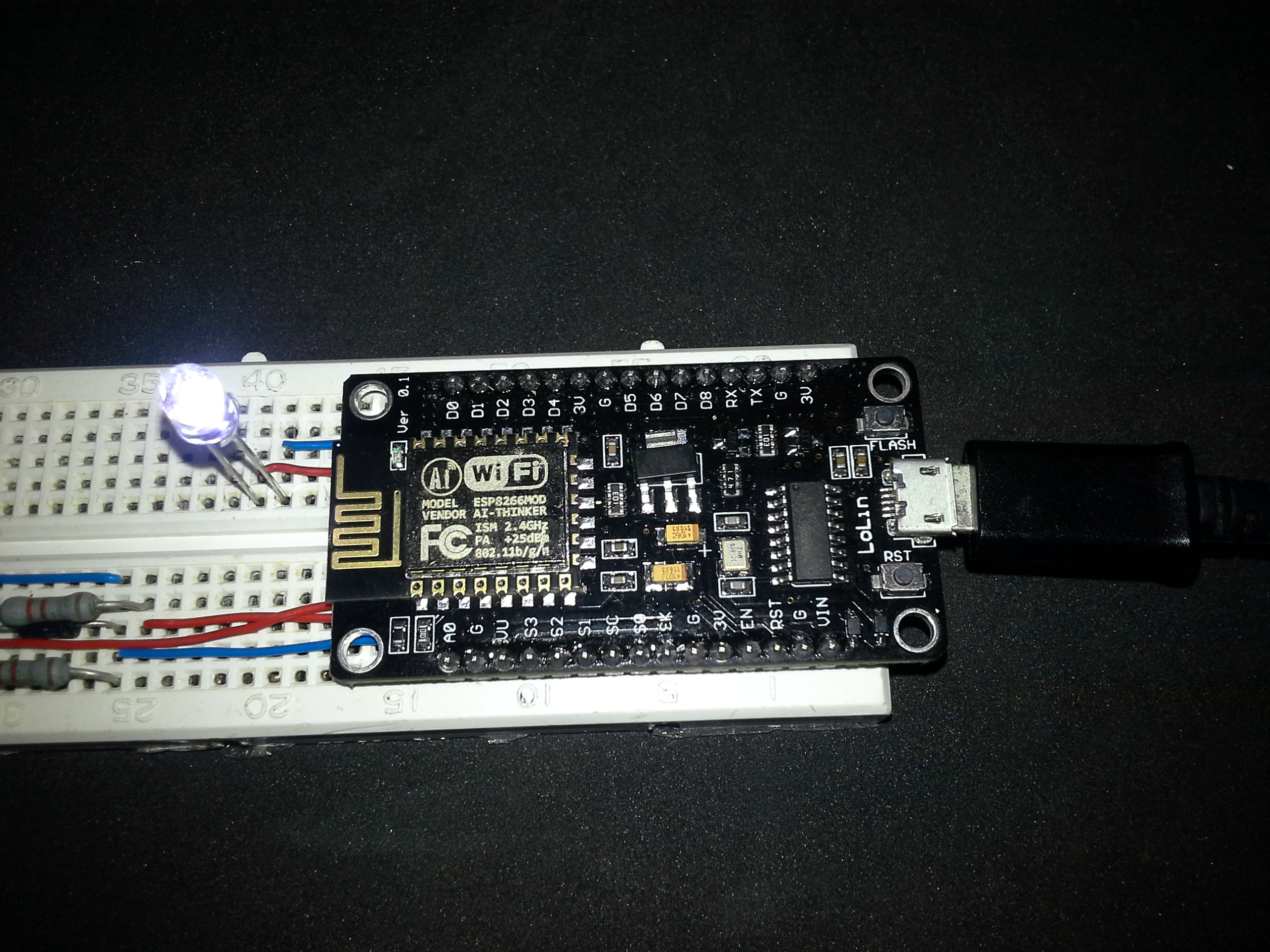
Mounting
Downloads GiHub – Arduino IDE
References
Introduction Platform IoT Blynk & ESP8266
Introduction Platform IoT Cayenne mydevices & ESP8266
Introduction IoT Platform aREST.io
Testing Industrial Platform Groov and ESP8266 NodeMCU
Installation Mosquitto Broker MQTT in lubuntu (Ubuntu) Linux