For some months I have a PLC Lollette, in one of our previous videos indicate how to download the programming software demo version Tutorial Installation Gx Works2 Demo for Programming PLC LE3U FK3U Lollette, in this opportunity we will make a brief characterization and disarming the PLC which cost less than 30 dollars!.
We will analyze a little its functionality and the characteristics in possible applications.
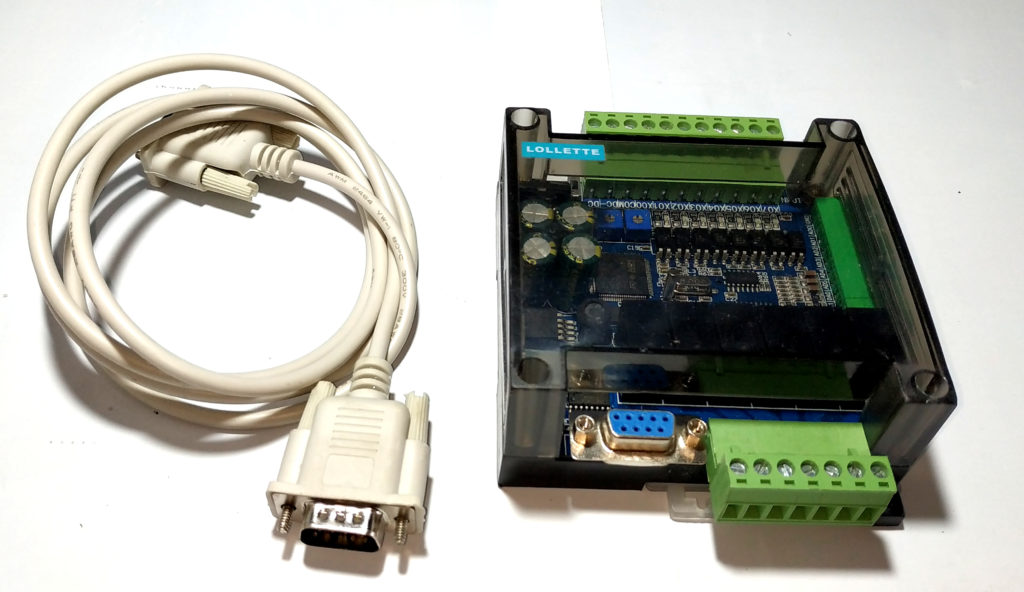
I bought this PLC in the online store Aliexpress, there are many versions and variations that I have is the FK3U or FX3U / LE3U 14MR6AD2DA or LE3U-14MR or LE3U 14MR6AD2DA technically all versions are similar and maybe equal, brings PLC Lollette with housing, “some versions are directly the PLC“ and a Serial DB9 male-female cable.
Materials and Where to Buy
Features
List of features according to manufacturer:
- Power Supply 24 VDC
- Brand: Lollette
- Model: LE3U 14MR6AD2DA
- Supply voltage: 24 VDC
- Digital inputs: 8
- Digital outputs: 6
- Type of outputs: relay
- Output capacity: 5A @ 250 VAC
- Analog ports: 6
- Communication ports: RS232, Communication ports: RS485
- Supports HMI: Yes
- HMI compatible model: OP320-A
- Supports Encoder: Yes
- MCU: 32-bit
- Speed: 3 kHz
- Program capacity: 8,000 lines of LADDER
- DIN rail mounting: Yes
Among interesting things, digital inputs can be configured as high-speed counters and functions for encoders.
- Supports 16-bit encryption,
- Supports three types of interruptions,
- 485 communication compatible with 4 types of communication protocols,
- Support 1N, 2N, 3U of the instructions.
- Scan 3000 steps 1 ms
Possible Applications
Well those of us who have already programmed a PLC know that it was designed for industrial applications and its hardware characteristics and programming language vary with the known arduino or any other microcontroller platform.
• Proximity sensors
• Capacitive sensors
• Thermometers
• Outputs for relays
• Analog potentiometer inputs or other analog devices
• Proportional analog outputs
• Communication ports with HMI and other PLCs
Connections Diagram
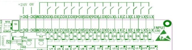
This very little documentation about the connections, from many searches I have found this connection diagram, which although it is a version with more inputs and outputs are very similar.
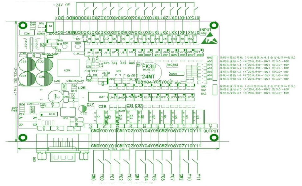
The lollette manufacturer talks about their specific references about these PLCs.
They are relatively cheap, totally in agreement.
• Avoid the use of long chains of relays (RELAYS) (electro-mechanical programming)
• Its programming language is simple and friendly, LADDER and SFC.
• Specialized code knowledge is not required, only requires documentation on (Sequential Logic) ladder one of the most used and learn to use the programming software.
• Very fast response times, totally in agreement.
• Reliable system stability, totally in agreement.
• Variety of configurations and ports adaptable to the needs of any application, in total agreement.
If you mention that your PLCs are 100% compatible with the Mitsubishi Developer (Mitsubishi Firmware), it seems perfect since it is a very used system tested for its reliability and friendly use.
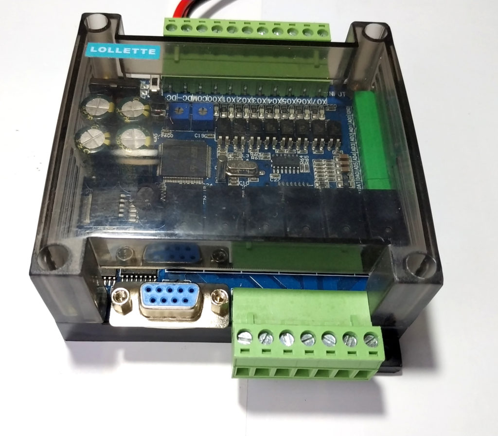
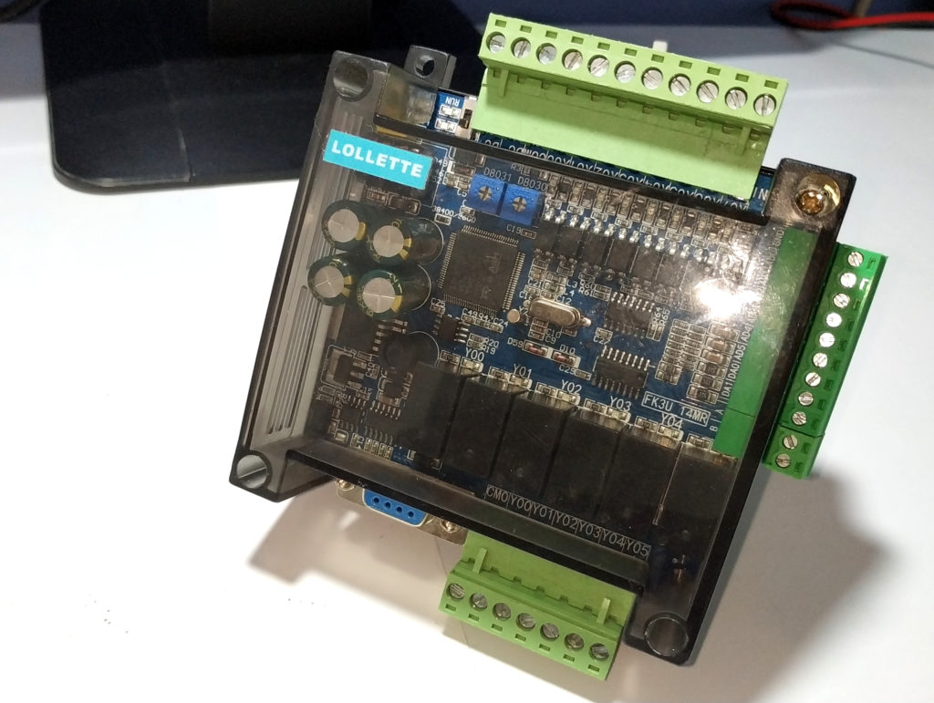
Disarming the PLC
Disarming it is not of great complexity thanks to its simplicity at the shell level, compared to other PLCs I have disarmed a Panasonic plc similar to the one disarmed by a colleague of absolutelyautomation.com: Panasonic FPX-C14R PLC teardown.
technically they are 4 screws.
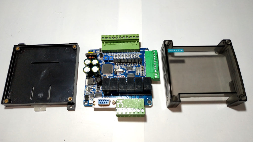
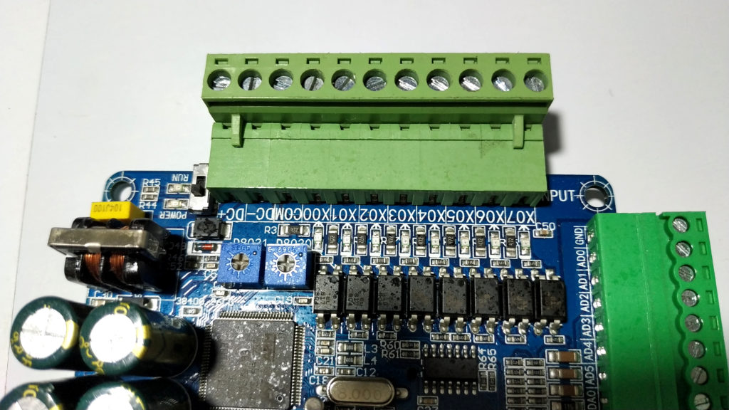
The terminals or terminals are removable, perfect for disconnecting wiring.
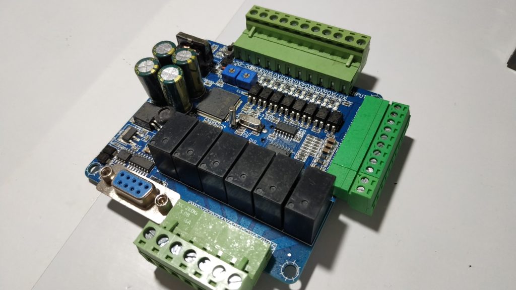
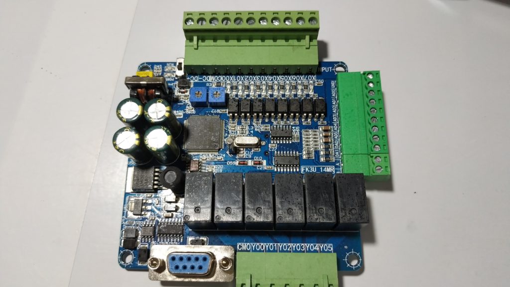
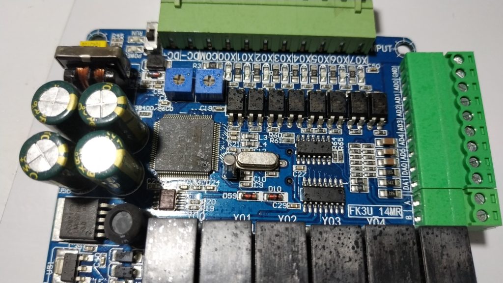
Top side view.
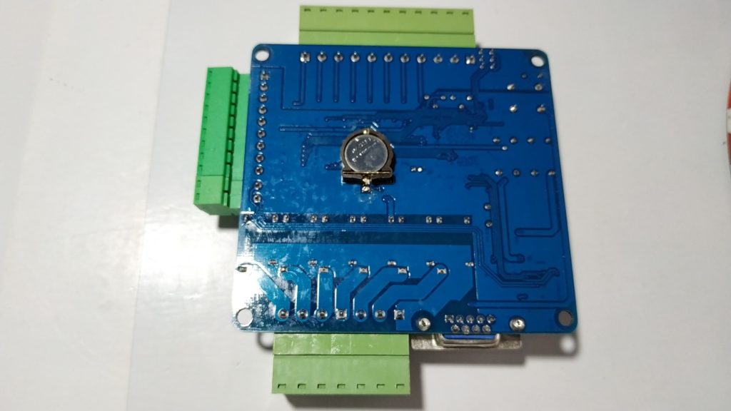
Bottom side view
It has a battery for the RTC “Real Time Clock”.
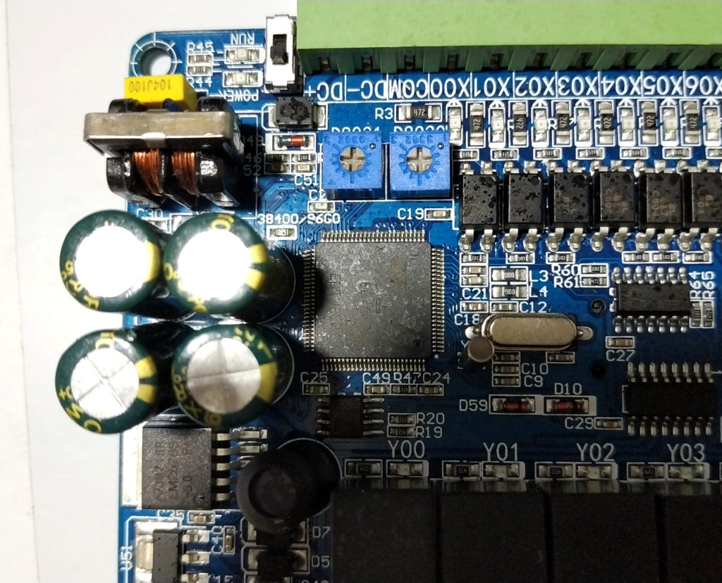
Apparently it uses an ARM STM32F103 CORTEX M3, I can not see the exact reference, but it contains firmware compatible with Mitsubishi PLC.
I observe 2 blue potentiometers D8031 and D8030, I suppose that each one is technically an ADC and write PLC registers, it has many applications, parametrization settings of Timer, Offset among other functions.
Digital Inputs
The 8 digital inputs are well insulated with optocouplers, you must be careful with the polarization of these inputs, take into account the connection diagram
Note: You only have to make connections between COM and the required inputs, example COM-X0, you must be very careful with the type of sensor either NPN or PNP, this test I have still done, for future tutorials.
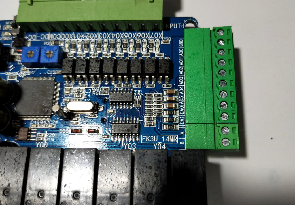
6 ADC and 2 DAC
This version has 6 analog inputs and 2 analog outputs, without me being an expert in electronic design I see that they are not isolated attention! .
- 3 analog inputs 0 to 10 volts
- 3 analog inputs 0 to 20 milliamps
- 2 Analog outputs 0 to 10 volts.
In my experience with analog electronics, the part of analogue inputs and outputs is very complex, according to 14-pin integrated observation it is apparently that an LM324 “quadruple operational amplifier simple power” is used.
Usually the ADC and DAC part should be isolated either by transformers or any other method, I personally recommend to be very careful with the connection since being not isolated, some short in some output or input could damage the CPU or all the PLC circuit.
Following the analog outputs we can see the 2 terminals of the RS485 serial port.
We can observe a 16-pin integrated near the relays, is a ULN2003 has internally 7 drivers for power control of the relay coils.
This version has 6 relay outputs with a single common, according to the connection diagram all contacts are normally open.
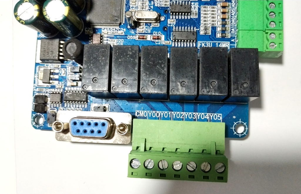
We can observe the switch that changes from programming mode to RUN, really the programming software can also make that change remotely, the switch must be left in RUN, otherwise if the PLC goes off the program would stop.
If I do not mention it before, this PLC is powered by 24 Volts, in the terminals DC + and DC- we see a transformer referring to the source, it must be a DC-DC converter, it has some capacitors and it uses the switching voltage regulator LM25765, It has AMS1117 to 5v.
Video: Review #PLC Lollette FX3U 14MR / LE3U / FX3U / FX3UC: Part 1 Hardware
Programming Software
Since this PLC is technically similar to a Mitsubishi PLC, the programming software is the Developer Gx Works, it is only available for Windows, in my case I use linux and I have simply created a virtual machine (VirtualBox) and installed the demo Free GxWorks2 version for 60 days, I indicate where to download it and install it in the following Tutorial.
First Programming Test
Conclusions
For less than 30 dollars, which cost me this PLC, I think it is more reasonable to use a Lollette than to place an Arduino or I design or assemble everything from scratch.
Well I think it’s important to use robust in certain applications, well it does not compete with an Allen Bradley PLC or Siemens PLC, but it gives me peace of mind for certain basic applications, and I personally would not have the time or resources to develop something similar and much less for this cost.
Not only do I see the advantages of a tried and tested hardware, I also consider analyzing that it uses a stable and secure programming platform I speak of the GX Works, Debugging and programming, this small PLC already has communication protocols, compatibility with other screens, connection with OPC , High speed counters.
On the other hand I also do not doubt the quality of lollette, but you have to be careful with the applications, not place it for the control of takeoff of Antonov, or very complex systems.
I personally am considering using them for monitoring and perhaps basic control, I will take the time to test it, I relied on digital inputs and outputs.
Not everything is flowers with this PLC, as mentioned analog electronics is complex and expensive talking specifically about the analog outputs and inputs, in the case of this PLC does not have these isolated channels, and for this price I am given more than I deserve, but I notice I feel distrust in connecting 4-20 ties in general analogous inputs and outputs, perhaps because if there is a short circuit it could damage the whole PLC, well they are only paranoid speculations, I will perform tests and publish them.
Regarding GXWorks, if I see the profitability of the application I will consider buying a license for the programming software.
I recommend it for ..
- No need to make simple basic applications and high level of risk.
- If you are not an experienced programmer in languages such as C,
- C ++, js and have or even if you have no knowledge about LADDER language.
Qualification
In final conclusion regarding the following parameters I will rate confidence from 0 to 100%:
- Hardware characteristics, robustness and 90% quality.
- Stability Programming and Debugging Software 100%.
- Programming language LADDER and SFC 100%
Next implementations
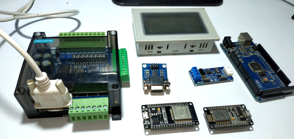
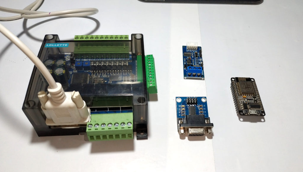
I will carry out tests of this plc with other platforms, both hardware and software, as a requirement I will try with arduino, esp8266 but the purpose is to implement the communication with ESP32 and also with Node-RED.
ESP32+MAX232 + PLC Lollette or ESP32 +RS485 + PLC Lollette
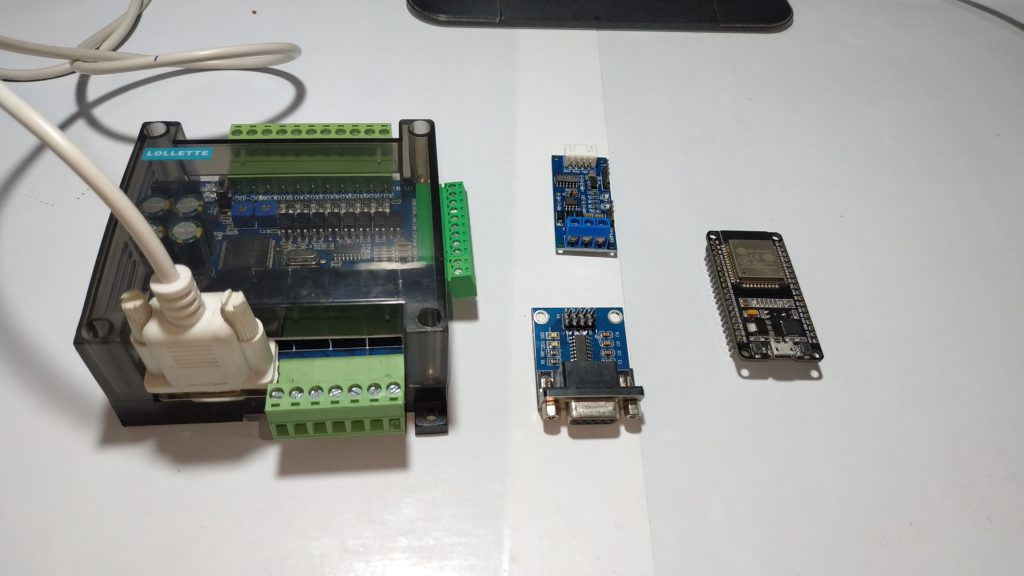
ESP8266+MAX232 + PLC Lollette or ESP8266+RS485 + PLC Lollette
Hi. Thank you for your review above. Based on the information from you site, I bought one unit of this LE3U 14MR. Everything was good. However, i cant seems to utilise my RTC module. When I checked my D8013, the second is not moving. And on top of that, I cannot rewrite my RTC time. Can you please help me with this?
Initially thank you very much, for visiting us, I have not yet performed tests with the RTC, I will take it into account for future tutorials, I am about to resume tests with this PLC, Thanks again